Heatilator • BCBV36 • 4008-033 • Rev P • 8/12 17
In addition to these framing dimensions, also reference the
following sections:
• Clearances and Mantel Projections (Sections 3.C. and 3.D.)
• Vent Clearances and Framing (Section 6)
39-3/4 in.
(1010 mm)
44 in.
(1118 mm)
44 in.
(1118 mm)
1 in. (25 mm) min.
appliance
to combustibles
Alcove
Installation
19-1/4 in.
(486 mm)
39-3/4 in.
(1010 mm)
39-3/4 in.
(1010 mm)
19-1/4 in.
486 mm
Drywall
48 in.
(1219 mm)
maximum
40-3/4 in.
(1035 mm)
5
Framing and Clearances
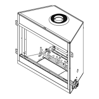
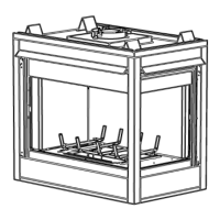
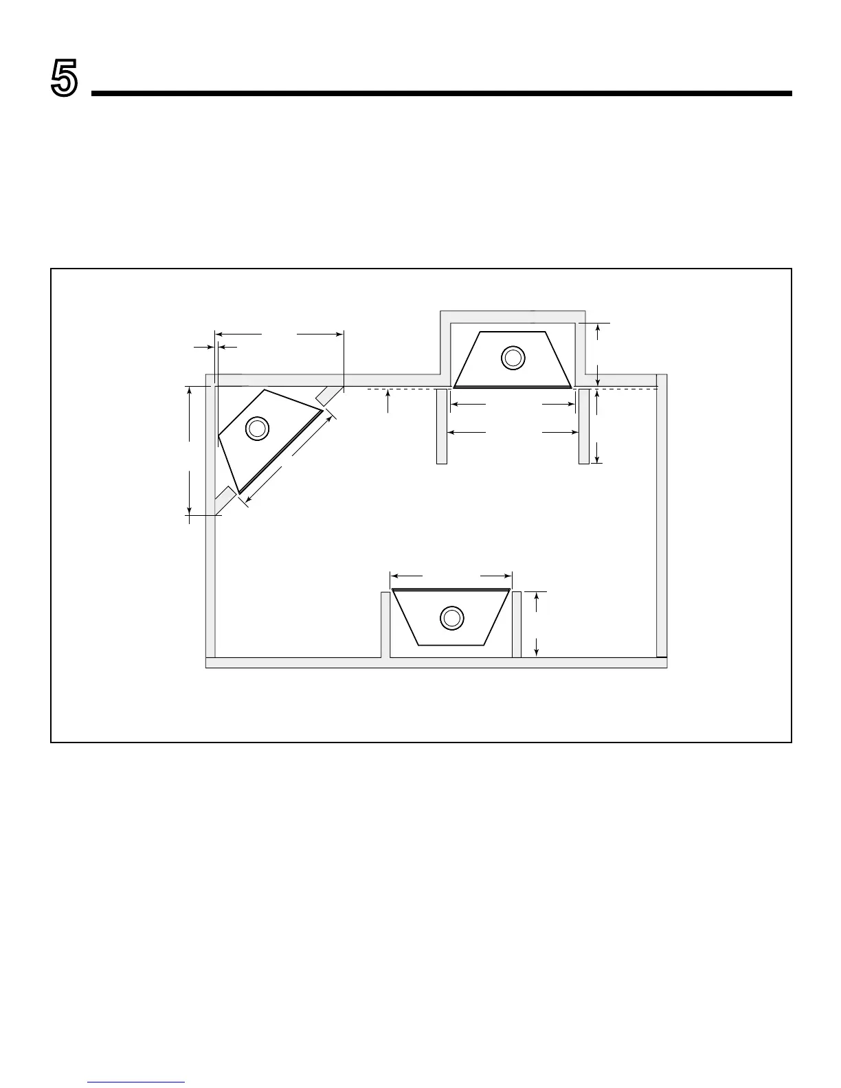
A. Select Appliance Location
When selecting a location for the appliance it is important
to consider the required clearances to walls (see Figure
5.1).
WARNING! Risk of Fire or Burns! Provide adequate
clearance around air openings and for service access. Due
tohightemperatures,theapplianceshouldbelocatedout
oftrafcandawayfromfurnitureanddraperies.
NOTICE: Illustrations reect typical installations and are
FOR DESIGN PURPOSES ONLY. Illustrations/diagrams
are not drawn to scale. Actual installation may vary due to
individual design preference.
Figure 5.1 Appliance Locations
Framing dimensions are the same with or without outside air.
B. Construct the Appliance Chase
A chase is a vertical box-like structure built to enclose the
gas appliance and/or its vent system. In cooler climates
the vent should enclosed inside the chase.
NOTICE: Treatment of ceiling restops and wall shield
restops and construction of the chase may vary with the
type of building. These instructions are not substitutes for the
requirements of local building codes. Therefore, you MUST
check local building codes to determine the requirements
to these steps.
Chases should be constructed in the manner of all out-
side walls of the home to prevent cold air drafting prob-
lems. The chase should not break the outside building
envelope in any manner.
Walls, ceiling, base plate and cantilever oor of the chase
should be insulated. Vapor and air inltration barriers
should be installed in the chase as per regional codes for
the rest of the home. Additionally, in regions where cold
air inltration may be an issue, the inside surfaces may
be sheetrocked and taped for maximum air tightness. To
further prevent drafts, the wall shield and ceiling re-
stops should be caulked with high temperature caulk to
seal gaps. Gas line holes and other openings should
be caulked with high temp caulk or stuffed with unfaced
insulation. If the appliance is being installed on a cement
slab, a layer of plywood may be placed underneath to
prevent conducting cold up into the room.