24 / 44
PL
SK
DE
EN
CS
HU
UNPACKING
• Carefully check all parts after unpacking the product from the box.
• Do not throw away packaging materials until you have not reviewed carefully if they did not
remain a part of the product.
• Parts of the packaging (plastic bags, paper clips, etc.) do not leave within reach of children,
could be a possible source of danger. There is a danger of swallowing or suffocating!
• If you notice transport damage or while unpacking, notify your supplier immediately. Do not
operate the product!
• We recommend save the package for future use. The packaging materials must still be
recycled or disposed of in compliance with the relevant legislation. Sort different parts of
the packaging according to material and hand it to the appropriate collection sites. For
further information contact your local administration.
C Fasteners can become loose during transport in the packaging.
PACKAGE CONTENTS
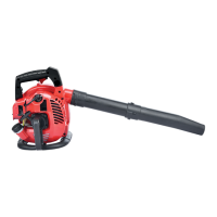
1x machine body, 1x straight blower tube, 1x end vacuum tube, 1x vacuum upper tube, 1x
blower nozzle tube, 1x dust bag, 1x elbow tube, 1x manual for use
• Standard accessories are subject to change without notice.
• This product requires assembly. The product must be assembled correctly before use.
ASSEMBLY
Note: I
Assemble the parts of blower tube as shown and tighten everything.
WARNING! B
Disconnect the spark plug before performing any service on the machine. Wait till
all moving parts are completely stopped.
Never run the unit without the proper equipment attached. When used as a blower,
always install the blower tubes and close the cover. When used as a vacuum, always
install the vacuum tubes and vacuum bag. Make sure the vacuum bag is completely
zipped when the unit is running to avoid flying debris.
ASSEMBLING THE BLOWER
1. Loosen the clamp bolt (fig. 3A) at the blower outlet.
2. Align the rib (fig. 3B) on the upper blower tube with the groove in the blower outlet and
slide the tube (fig. 3C) into place.
3. Secure the tube by turning the bolt clockwise.
4. Assemble the a blow tube and the tube with nozzle (fig. 4A). Align the slots on the lower
blower tube with the tabs (fig. 4B) on the upper blower tube. Slide the lower blower tube
onto the upper blower tube. Turn the lower blower tube clockwise until a click is felt to
secure the lower blower tube to the upper blower tube. When the tubes are assembled
together properly, the arrows (fig. 4C) on both tubes will be aligned.