8 Programming: Cycles
162
ú
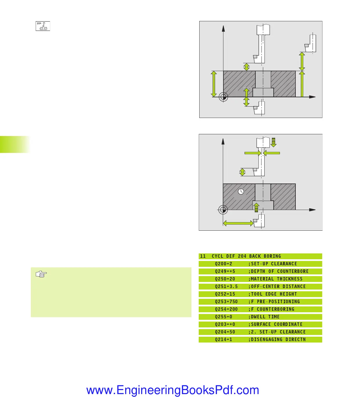
Set-up clearance Q200 (incremental value): Distance
between tool tip and workpiece surface.
ú
Depth of counterbore Q249 (incremental value):
Distance between underside of workpiece and the
top of the hole. A positive sign means the hole will be
bored in the positive spindle axis direction.
ú
Material thickness Q250 (incremental value): Thickness
of the workpiece
ú
Off-center distance Q251 (incremental value): Off-
center distance for the boring bar; value from tool data
sheet
ú
Tool edge height Q252 (incremental value): Distance
between the underside of the boring bar and the main
cutting tooth; value from tool data sheet
ú
Feed rate for pre-positioning Q253: Traversing speed
of the tool when moving in and out of the workpiece,
in mm/min
ú
Feed rate for counterboring Q254: Traversing speed of
the tool during counterboring in mm/min
ú
Dwell time Q255: Dwell time in seconds at the top of
the bore hole
ú
Workpiece surface coordinate Q203 (absolute value):
Coordinate of the workpiece surface
ú
2nd set-up clearance Q204 (incremental value):
Coordinate in the tool axis at which no collision
between tool and workpiece (clamping devices) can
occur.
ú
Disengaging direction (0/1/2/3/4) Q214: Determine the
direction in which the TNC displaces the tool by the
off-center distance (after spindle orientation).
1: Displace tool in the negative main axis direction
2: Displace tool in the negative secondary axis direction
3: Displace tool in the positive main axis direction
4: Displace tool in the positive secondary axis direction
Danger of collision!
Check the position of the tool tip when you program a
spindle orientation to 0° (for example, in the Positioning
with Manual Data Input mode of operation). Align the
tool tip so that it is parallel to a coordinate axis. Select a
disengaging direction in which the tool can plunge into
the hole without danger of collision.
8.2 Drilling Cycles
X
Z
Q250
Q203
Q204
Q249
Q200
Q200
X
Z
Q255
Q254
Q214
Q252
Q253
Q251
Example NC blocks:
11 CYCL DEF 204 BACK BORING
Q200=2 ;SET-UP CLEARANCE
Q249=+5 ;DEPTH OF COUNTERBORE
Q250=20 ;MATERIAL THICKNESS
Q251=3.5 ;OFF-CENTER DISTANCE
Q252=15 ;TOOL EDGE HEIGHT
Q253=750 ;F PRE-POSITIONING
Q254=200 ;F COUNTERBORING
Q255=0 ;DWELL TIME
Q203=+0 ;SURFACE COORDINATE
Q204=50 ;2. SET-UP CLEARANCE
Q214=1 ;DISENGAGING DIRECTN
kkap8.pm6 30.06.2006, 07:03162
www.EngineeringBooksPdf.com
 Loading...


