!
WARNING
ELECTRICAL OPERATION HAZARD
Failure to follow this warning could result in
personal injury or death.
Before installing or servicing unit, always turn off
all power to unit. There may be more than 1
disconnect switch. Turn off accessory heater
power if applicable. Lock out and tag switch with a
suitable warning label.
!
CAUTION
CUT HAZARD
Failure to follow this caution may result in personal
injury.
Sheet metal parts may have sharp edges or burrs.
Use care and wear appropriate protective clothing
and gloves when handling parts.
NOTE
: Read the entire instruction manual before starting
installation.
These instructions must be read and understood
completely before attempting installation.
TA BLE OF CONTENTS
PAGE
damage.
NOTE
is used to highlight suggestions which
will
result in enhanced installation, reliability, or operation.
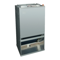
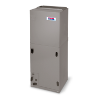
INTRODUCTION
FMA4X, FMA4P Fan Coils are designed with application
flexibility in mind and are suitable for closet and flush mount
installations. Units are available with field- installed electric
SAFETY CONSIDERATIONS . . . . . . . . . . . . . . . . . . . . . . . . . 1
heat with circuit breaker. Units are used indoors as the fan
INTRODUCTION
............................................................................
1
coil for split- system heat pumps or air conditioners. The
FMA4P uses a ref
rigerant piston metering device and a 3
INSTALLATION
. . . . . . . . . . . . . .... . . . . . . . . . .... . . . . . . . 2
Speed PSC Motor. FMA4X uses a TXV and a 5 speed
Step 1 — Check Equipment . . . . . . . . . . . . . . . . . . . . . . . . . 2
multi- tap ECM motor for efficiency. Units are available in
Step 2 — Mount Fan Coil .... . . . . . . . . . .... . . . . . . . . . . 2
18,000 through 36,000 Btuh nominal cooling capacities.
Field- installed heaters are available in 5, 7.5, and 10 kW
Step 3 — Ductwork S
pecifications
...........................................
4
Step 4 — Condensate Drain
.......................................................
4
sizes. The coil is equipped with sweat- type connections and
is vapor- charged with dry nitrogen.
Step 5 — Electrical Conne
ctions . . . . . . . . . . . . . . . . . . . . . 4
Step 6 — Select Proper Blower Speed
...................................
5
Step 7 — TXV . . . . . . . . . . . . . . . . . . . . . . . . . . . . . . . . . . . . 6
NOTE
: Nuisance sweating may occur if the unit is installed in
START-UP
......................................................................................
6
SEQUENCE OF OPERATION
.......................................................
6
CARE AND MAINTENANCE
........................................................
6
a humid location with low airflow.
Units are designed for upflow applications only. Local codes
may limit th
is free - air - return type unit to instal
lation in
single- level applications.
AIRFLOW PERFORMANCE TABLES . . . .... . . . . . . . . . . . 7
SAFETY CONSIDERATIONS
Improper installation, adjustment, alteration, service,
maintenance, or use can cause explosion, fire, electrical
shock, or other conditions which may cause death, personal
injury or property damage. Consult a qualified installer,
service agency, or your distributor or branch for information or
assistance. The qualified installer or agency must use
factory
-
-
-
authorized kits or accessories when modifying this
product. Refer to individual instructions packaged with kits or
accessories when installing.
Follow all safety
codes. Wear safety glasses, protective
clothing, and work gloves. Use quenching cloth for brazing
operations. Have a fire extinguisher available. Read these
instructions thoroughly and follow all warning or cautions
included in literature and attached to the unit. Consult local
building codes and the current editions of the National
Electrical Code (NEC) NFPA 70.
In Canada, refer to the current editions of Canadian Electrical
Code CSA C22.1.
Recognize safety information. This is the safety alert symbol
. When you see this symb
ol on the unit and in instructions
or manuals, be alert to the potential for personal injury.
Understand the signal words
DANGER
,
WARNING
, and
CAUTION
. These words are used with the safety alert
symbol.
DANGER
identifies the most serious hazards which
will
result in severe personal injury or death.
WARNING
signifies hazards which
could
result in personal injury or
death.
CAUTION
is used to identify unsafe practices, which
may
result in minor personal injury or product and property
Specifications subject to change without notice.
496 01 8001 04 25/6/17
INSTALLATION
INSTRUCTIONS
APARTMENT FAN COIL UNIT
FMA4X, FMA4P
!
WARNING
EXPLOSION HAZARD
Failure to follow this warning could
result in death, serious personal
injury, and/or property damage.
Never use air or gases containing
oxygen for leak testing or operating
refrigerant compressors. Pressurized
mixtures of air or gases containing
oxygen can lead to an explosion.
!
for installation in conditioned spaces only.
This unit is approved