5
Parker Hannifin Corporation
Helac/Cylinder Division
Enumclaw, Washington USA
www.helac.com
Helical, Hydraulic Rotary Actuators
L20 Series Service & Repair Manual
Catalog HY34-1120
Operation Technology
Operation Technology
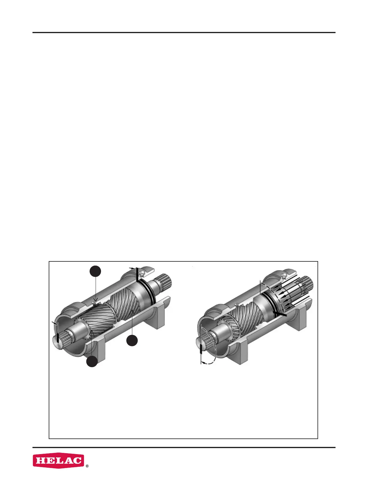
The L20 Series rotary actuator is a simple
mechanism that uses Helac's sliding spline
technology which converts axial piston motion
into powerful shaft rotation. As seen in the
illustration below left, each actuator is composed
of a housing with an integral ring gear (1) and
only two moving parts: the central shaft (2),
and the annular piston sleeve (3). Note the L20
actuator shaft features an integral mounting
ange and bearing which are not shown in the
illustration.
Helical spline teeth machined on the shaft
engage matching splines on the inside diam-
eter of the piston. The outside diameter of the
piston carries a second set of splines, of opposite
hand, which engage the matching splines of the
housing's ring gear.
As hydraulic pressure is applied, the piston is
displaced axially within the housing - similar
to the operation of a hydraulic cylinder - while,
simultaneously, the splines cause the shaft to
rotate. When the control valve is closed, oil is
trapped inside the housing, preventing piston
movement and locking the shaft rmly in position.
The shaft is supported radially by the large upper
radial bearing and the lower radial bearing (see
drawings on pages 8 and 9). Axially, the shaft
is separated from the housing by the upper and
lower thrust washers. The end cap is adjusted
for axial clearance and locked in position by set
screws or pins.
The L20 Series is available in several dierent
sizes. All L20 Series actuators have the same
internal design and basic components, though
congurations of parts may be slightly dierent
depending on model.
Many L20 actuators are equipped with factory
installed counterbalance valves, which perform
four major functions.
• Protects the actuator in the event of overload
• Enables the actuator to hold position without
drifting when external loads are applied
• Reduces hydraulic backlash by pressuring
the hydraulic uid
• Provides a constant controlled rate of rotation
in over-center load conditions
Bars indicate starting positions of piston
and shaft. Arrows indicate direction they
will rotate. The housing with integral ring
gear remains stationary. For clarity, the
shaft ange, bearings, and end cap are not
shown.
Applying uid pressure will displace the
piston axially while the helical gearing causes
the piston and shaft to rotate simultaneously.
The double helix design compounds rotation:
shaft rotation is about twice that of the piston.
Applying pressure to the opposite port will
return the piston and shaft to their original
starting positions.
3
2
1
 Loading...