68
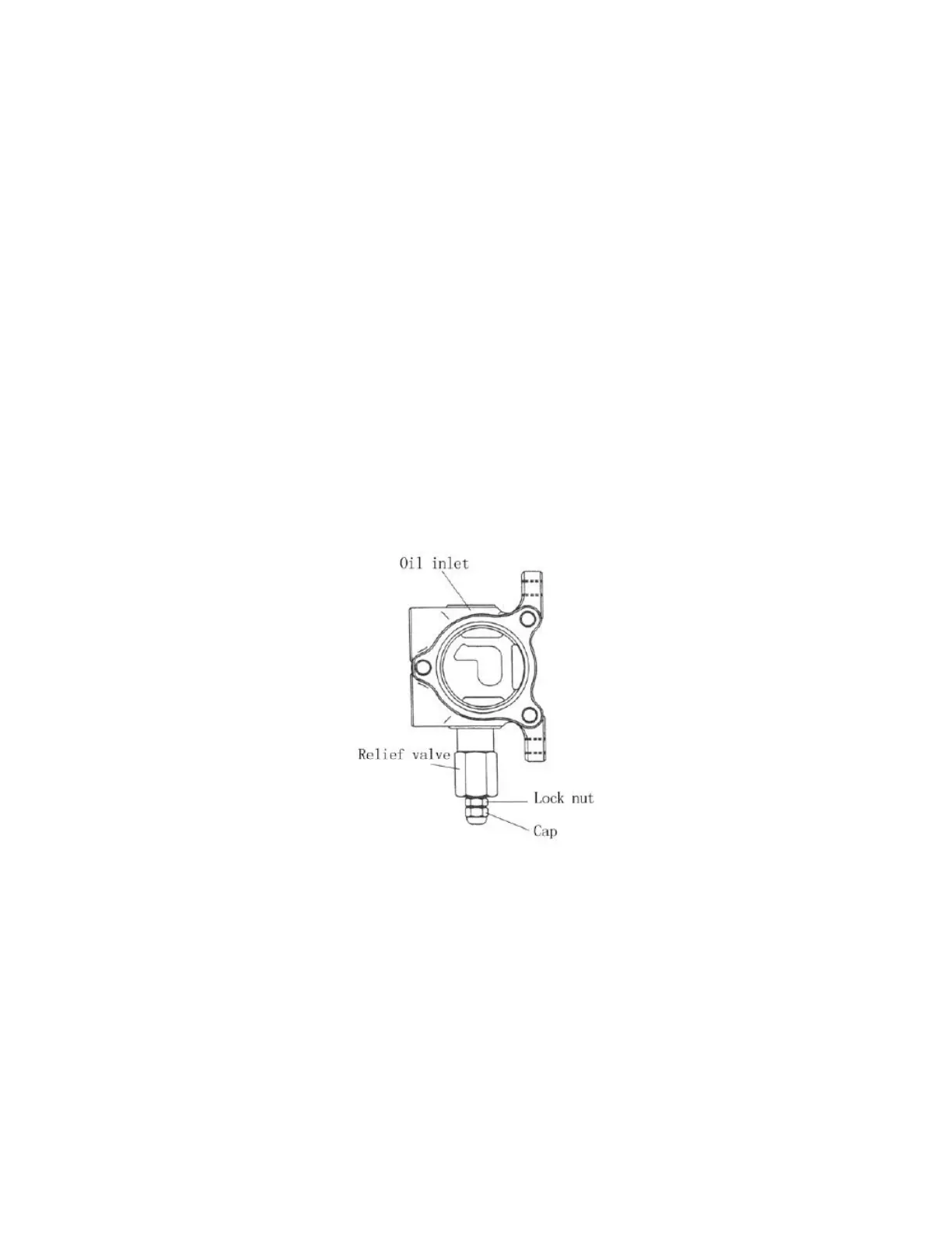
(5) Setting pressure of the control valve (See Fig. 5-15)
The pressure of the safety valve shall not be adjusted by non-professional personnel.
The adjustment shall follow following procedures:
a) Screw off the plug of the measuring hole on the inlet of the control valve. Install
an oil pressure gauge capable of measuring 25MPa.
b) Operate tilting lever and measure the pressure at the end of the cylinder stroke.
c) If the oil pressure is different with the specified value, loosen the locking nut of
the relief valve and turn the adjusting screw left and right until the pressure reaching the
specified value. Turn left when the pressure is high and turn right when the pressure is
low.
d) Tighten the nut after adjusting.
Fig. 5-15
5.1.3 Lift cylinder
The lift cylinder is of single-acting piston type. It consists of cylinder body, piston,
piston rod, cylinder cap, cut-off valve and oil seals. The cylinder head is equipped with
bushing and oil seal and the bushing supports the piston rod and the oil seal keeps dust
off. (See Fig. 5-16)
 Loading...