12
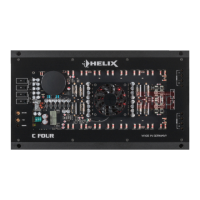
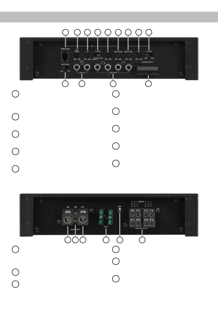
Connectors and control units
11
GND
Connector for the ground cable (negative
terminal of the battery or metal body of the
vehicle).
12
REM
Connector for the remote cable.
13
+12 V
Connector for the +12 V power cable of the
positive terminal of the battery.
14
Fuse
Input fuses - 2 x 30 Ampere.
15
Power & Protect LED
This LED indicates the operating mode of the
amplier.
16
Output Channels
Speaker outputs for connecting speaker
systems.
1
Remote (C/D)
Input for connecting the included cable re-
mote control for volume adjustment of the
channels C and D in bandpass mode.
2
Input Mode
Switch to route input signals to respective
amplier channels.
.
3
Bass Boost
Control for adjusting the bass boost on
channels C and D from 0 to 12 dB.
4
Line Out
RCA outputs for connecting external ampli-
ers.
5
LPF
Control for adjusting the lowpass lter of the
channels C and D from 40 to 4,000 Hz.
6
X-Over
Switch for activating the lters for each
channel pair.
7
HPF
Control for adjusting the highpass lter from
15 to 4,000 Hz.
8
Line Input
RCA inputs for connecting pre-amplier
signals.
9
Input Level
Control for adjusting the input sensitivity of
the Line and Highlevel Inputs.
10
Highlevel Input
Highlevel speaker inputs for connecting a
factory radio or an aftermarket radio without
pre-amp / line outputs.
11 12 1513 14 16
1 3 5 6 7 9
2
10
4 8
9 7 6
 Loading...