13
Initial start-up and functions
1
Remote C/D
This input is used to connect the included remote
control. The remote control allows you to control
the volume of the channels C and D in stereo and
bridged mode.
Note: Volume control via remote control is only ac-
tivated in bandpass mode.
2
Input Mode
This switch is used to route the input signals to the
respective amplier channels.
4-channel mode: If the head unit / car radio provides
two stereo outputs, all four speaker outputs are sup-
plied with the corresponding input signal.
2-channel mode: If the head unit / car radio only
provides one stereo output, all amplier channels
are supplied with this signal. This means, that only
the RCA / highlevel inputs of the channels A and B
need to be connected. In this mode the input signal
of channel A is routed to channel C and channel B is
routed to channel D. Please consider that the fader-
and balance control of the head unit have the same
effect on channels C and D as on channels A and B.
3
Bass Boost
This control is used to increase the bass response
at a center frequency of 45 Hz from 0 to 12 dB.
4
Line Out
2-channel pre-amplier output for connecting exter-
nal ampliers. The output voltage is 6 Volts max.
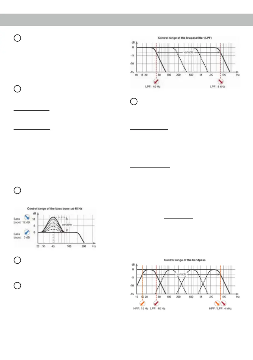
5
LPF
This control is used to adjust the crossover frequen-
cy of the lowpass lter of the channels C and D from
40 to 4,000 Hz.
6
X-Over
This switch allows to set the internal crossover to
highpass, fullrange or lowpass / bandpass mode.
The lter options depend on the channel pair.
Channel pair A/B: Highpass lter or fullrange
If this X-Over switch is set to HPF (highpass lter)
the crossover frequency for the highpass can be ad-
justed with control 7 of the channel pair A/B.
At switch position FULL (fullrange) the crossover is
bypassed.
Channel pair C/D: Lowpass lter resp. bandpass,
fullrange or highpass lter.
If this X-Over switch is set to HPF (highpass lter)
the crossover frequency for the highpass can be
adjusted with control 7 of the channel pair C/D. At
switch position FULL (fullrange) the crossover is
bypassed.
At switch position LPF (lowpass lter / bandpass)
the highpass is always active. That means a band-
pass is created in any case.
By adjusting the highpass (control 7) and lowpass
(control 5) lter any bandpass between 15 Hz and
4,000 Hz can be realized. Please note that the high-
pass has to be adjusted even if it is set to 15 Hz
(left stop).
Caution: To avoid a loss of gain make sure that
the crossover frequencies of the high- and lowpass
lters do have an interval of at least two octaves
when generating a bandpass.
That means if the lowpass signal is adjusted to
 Loading...