7
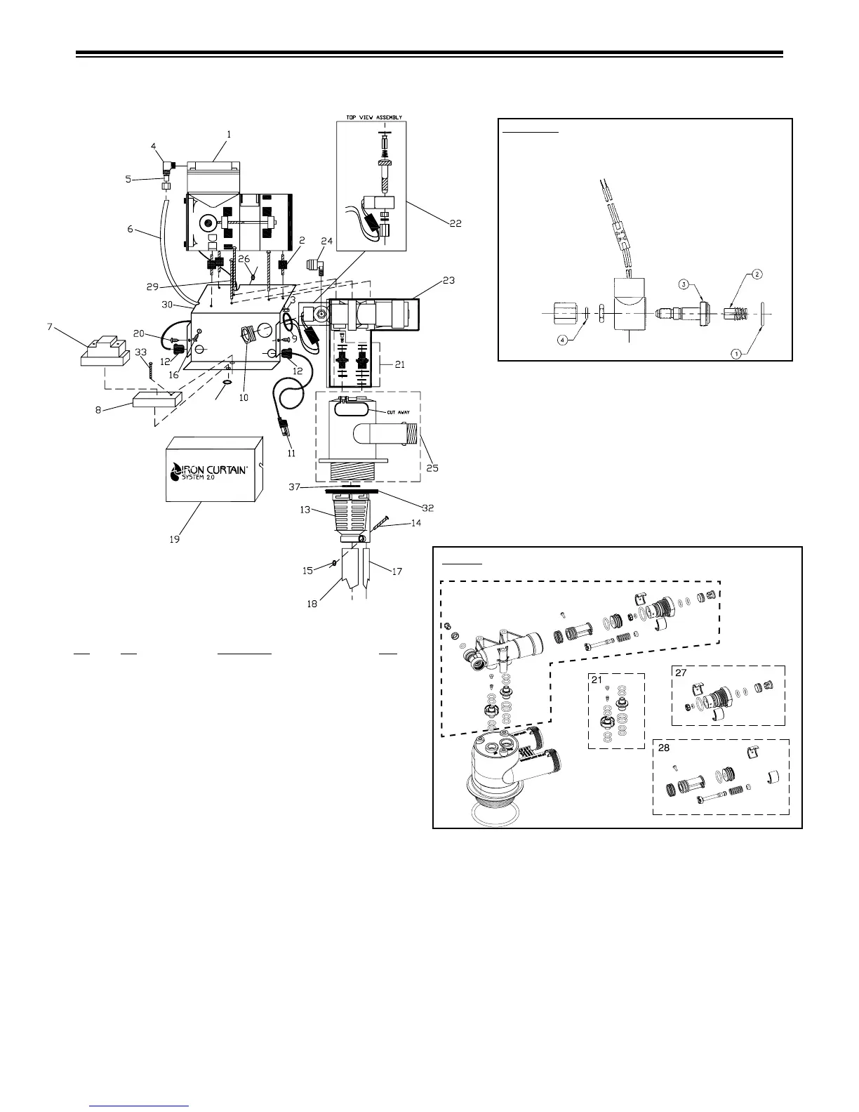
1 ...........110269 .................... Hellenbrand Pump ........................... 1
2 ...........101631 .................... IC Pump Feet ...................................3
3 ...........102137 .................... IC Pump Feet Nut ............................3
4 ...........110470 .................... Elbow, IC Pump 1/4” NPT x 1/4”
Tubing ..............................................1
6 ...........102666 .................... 1/4” Polypropylene Tubing ..............1
(9” required)
7 ...........108010 .................... Relay ................................................ 1
8 ...........108011 .................... Relay Base ....................................... 1
9 ...........102433 .................... Conduit Seal ....................................1
10 ...........101318 .................... Electrical Bushing, 1/2” ...................1
11 ...........103073 .................... Power Cord, 8 ft. .............................1
12 ...........103108 .................... Strain Relief, Elec. Cords ................. 2
13 ...........101547 .................... Upper Distributor Basket ................. 1
14 ...........102479 .................... Screw, Upper Distributor Basket
6-32 x 3/4” 8-18SS .......................... 1
15 ...........102133 .................... Nut, Upper Distributor Basket
6-32 316SS ...................................... 1
16 ...........102477 .................... Grounding Screw .............................1
17 ...........102247 .................... Bleed o Tube ..................................1
18 ...........102663 .................... Pick Up Tube ...................................1
19 ...........103469 .................... Cover
20 ...........102477 .................... Screw, Cover ...................................2
21 ...........101152 .................... Adapter Assembly Kit w/Duckbill
Check Valve Installed ......................1
22 ...........103914 .................... Solenoid Operator Assembly ...........1
22-RK .....103759 ....................
IC 2.0 Internal Solenoid Repair Kit
....1
23 ...........102847 .................... Shuttle Assembly ............................. 1
24 ...........100479 .................... 1/4” Vent Port Adapter ....................1
25 ...........101766 .................... Aeration Head .................................. 1
IC-2.0 Assembly
Item Part
No. No. Description Qty.
Item #23 - Shuttle Valve Assembly
(See Separated Items Below)
26 ...........107995 .................... Relay Base Nut ................................2
27 ...........101390 .................... End Cap Assembly ..........................1
28 ...........102259 .................... Piston Assembly ..............................1
29 ...........102476 .................... Back Plate Bolt ................................3
30 ...........108030 .................... Back Plate .......................................1
...........102792 .................... 1” Brass Inlet Check Valve (
Not Shown, See pg 7)
...........104174 .................... Vertical Adapter Inlet Check Valve
31 ...........104136 .................... Complete Aeration Assembly ..........1
32 ...........102192 .................... O’Ring-Tank Adapter .......................1
33 ...........107994 .................... Relay Base Screw ............................ 1
36 ...........102894 ....................
Solenoid Spanner Wrench (Not Shown)...1
37 ..........102165 .................... O’Ring Pick-Up Tube .......................1
1 = O'ring
2 = Plunger
3 = Guide Assembly
4 = Adapter O'ring
IC 2.0 Internal Solenoid Repair Kit
pn:103759
(Sold as a kit only, does not include coil assembly)
Coil Assembly
Item 103759
26
 Loading...