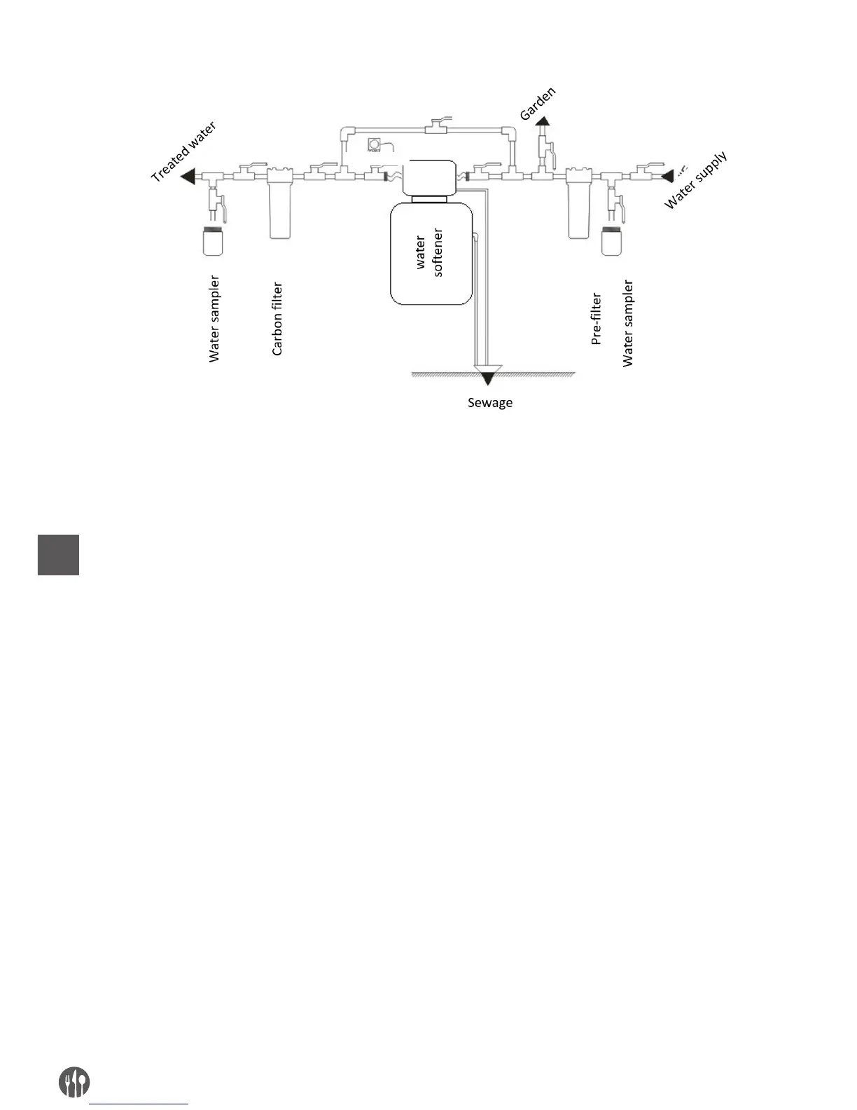
5.2. SAMPLE INSTALLATION DIAGRAM OF THE WATER TREATMENT SYSTEM
Diagram of the water treatment system
When installing and using the device:
• proper knowledge shall be possessed or profes-
sional services shall be commissioned
• it shall be ensured that the surface of installa-
tion is level and stable, as well as that the surface
will withstand the weight of the system filled with
water and salt tablets (in case of water softener)
• all connections shall be done in line with appli-
cable standards and provisions of law
• the device shall be connected to the existing wa-
ter installation with a flexible hose
• drainage to sewage shall be connected with
a flexible hose of the minimum hose diameter of
1/2”, of the length of the maximum of 6 m horizon-
tally
• solely and exclusively Teflon shall be used for
threaded seal-less connections
• the device shall be connected after all water in-
stallation connections are done
• perform resin regeneration after first connec-
tion
• periodically check water quality in order to en-
sure that the device operates properly
• use only the salt intended for water softeners, of
the purity of 99.5% minimum; use of fine salt pow-
der is prohibited
• the device shall be used in rooms of no excessive
air humidity and within the temperature range of
5 - 38°C
• use a reducing valve upstream the controller’s
water inlet if pressure exceeds 6.0 bar
• do not transport the device holding it by its hos-
es, the injector, the by-pass or other sensitive ele-
ments of the controller
• use the accessories and parts delivered by a dis-
tributor only
• protect the device against the access of children,
since they can damage or deregulate the controller.
100-240 VAC