9
T72007 A
HXL5
®
HUB MAINTENANCE PROCEDURES
A� If checking end play after installation, return to
INSPECTING HUB INSTALLATION on page13,
Step3�
B� If end play is more than 0.005” (0�127mm)�
Refer to CONTACTING HENDRICKSON Technical
Services for guidance on required next steps�
IMPORTANT: DO NOT place the suspension back into
service without correcting the problem�
C� If end play is within specication, no bearing
adjustment is necessary� Refer to Figure 13 on
page12 and check to ensure:
i� Spindle nut is secure�
ii� Interlock and tang are properly seated�
iii� Retaining screws are securely in place�
11� If not already done so, perform CHECKING FOR SEAL
LEAKS on page7�
12� Go to INSTALL HUBCAP on page13�
13� Reassemble brake wheel-end components�
REMOVING AND INSTALLING HUB
IMPORTANT: To ensure continued warranty, DO
NOT perform the following procedures
without obtaining prior authorization
from Hendrickson Trailer Technical
Services� Refer to CONTACTING
HENDRICKSON for contact information�
NOTE: In order to maintain warranty status,
CONTACTING HENDRICKSON is recommended
before removing the hubcap and disturbing the
precision spindle nut�
WARNING: Prior to performing maintenance
procedures, help ensure conditions
are safe by following section
PREPARING TRAILER FOR SERVICE on
page5.
HUB REMOVAL
Only after receiving proper authorization from
Hendrickson Technical Services, use the following
procedure to remove the HXL5
®
hub assembly:
1� Remove tire / wheel assembly�
2� Disengage brakes and:
If drum brake, remove brake drum�
If ADB equipped, remove the caliper�
3� Remove hubcap screws and remove hubcap,
discard gasket�
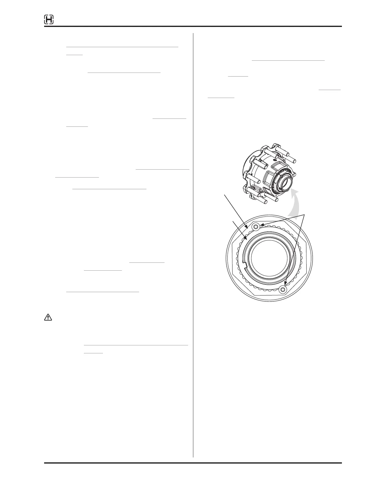
4� Using a hex key (TOOLS REQUIRED on page6),
remove button-head cap screws from interlock
washer Figure 7�
5� Remove interlock washer and spindle nut (Figure 1
on page5)�
NOTE: Pushing on edge of interlock washer near one
of the screw holes will cause the opposite edge
to tip away from the nut, allowing easy removal
of interlock washer�
Figure 7: Button-head cap screw on PRECISION240
®
or
PRECISION320
®
nut system
6� Carefully pull HXL5
®
hub assembly slightly toward
spindle end� A short quick motion should allow
outer bearing to exit the hub� Be prepared to catch
outer bearing if it slides off the end of the spindle�
Otherwise, simply remove it�
7� Remove hub from spindle. The inner bearing is
held in the hub by the hub seal and should come
off with the hub�
8� Remove and DISCARD HUB SEAL:
A� If the seal is in the hub - a pry bar can be
used to carefully remove the seal from the hub
bore� Damage to hub and hub surfaces must
be avoided�
Button-head cap
screw
Interlock washer
PRECISION240
®
or
PRECISION320
®
spindle nut