Page 8 For technical questions, please call 1-888-866-5797. Item 57675
SETUP - BEFORE USE:
Read the ENTIRE IMPORTANT
SAFETY INFORMATION section at the
beginning of this manual including
all text under subheadings therein
before set up or use of this product.
Note: For additional information regarding
the parts listed in the following pages, refer to
Parts List and Diagram on page 14.
Assembly
1. Slip the Dust Collection Bag over the
Dust Outlet behind the saw.
2. If adjustable and/or removable workpiece
support extension(s) are provided, always fix
and use these extension(s) during operation.
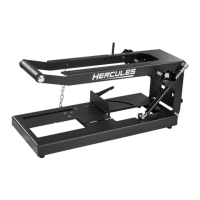
Mounting
1. Use the bolt holes in the Base to mount the
Miter Saw to a stable support before use.
Note: Mounting holes are provided in two sizes
to accommodate different sizes of hardware.
Mounting hardware not included.
2. Ensure that the Miter Saw is always stable
and secure (e.g. fixed to a bench).
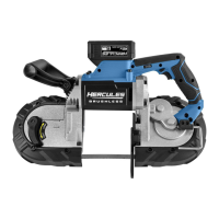
Saw Blade Selection
1. Any saw blade that will be used must be
marked as suitable for the material to be cut.
2. Use only a saw blade diameter in
accordance with the markings on the saw.
See specification table for the bore diameter
and the maximum kerf of the saw blade.
3. Use only saw blades that are marked with a speed
equal or higher than the speed marked on the tool.
Guard Setup
Check that the Lower Blade Guard is in place,
moves freely, and closes instantly.
Dust Extraction Setup
1. To use the Dust Collection Bag, slide the Bag
over the Dust Outlet at the rear of the Saw
Head Assembly. Refer to Assembly above.
2. Connect a dust extraction device (not
included) to the Dust Outlet to use a dust
collection system instead of the Dust Bag.
OPERATING INSTRUCTIONS
Read the ENTIRE IMPORTANT
SAFETY INFORMATION section at the
beginning of this manual including
all text under subheadings therein
before set up or use of this product.
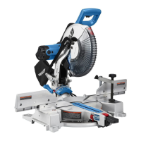
Tool Changing
1. Unplug the tool from its power source.
2. Pull out the Head Lock-Down Pin, raise the Saw
Head to the upper position, then raise the Lower
Blade Guard out of the way and hold it up.
3. Loosen the Guard Plate Bolt until it
disengages the Guard Plate.
4. Swing the Guard Plate up and out of
the way. Refer to Figure A.
Lower
Blade
Guard
Guard
Plate
Guard
Plate
Bolt
Figure A
5. Press in the Spindle Lock on the side
of the Saw Head and hold it in.
6. Remove the Arbor Bolt and Outer Flange. Refer to
Figure B.
IMPORTANT: The Arbor Bolt has a left-handed
thread and removes by turning CLOCKWISE.
Note: Make sure the Inner Flange
stays in place on the Spindle.
Outer
Flange
Inner
Flange
Spindle
Blade
Arbor Bolt
Figure B