10
CONNECT ELECTRICAL WIRING
Connect all remaining wires (power supply, engine
start-stop, etc.) according to the wiring diagram of the
crane/machine and the radio remote control.
Quick-Disconnect Plug (Optional)
The Quick-Disconnect plug shown is for the 250 x 250,
250 x 400, and 400 x 400 receivers. Different plugs are
provided for the HS-1 and 2 receivers.
The receiver may be equipped with a quick-disconnect
plug. The plug contains 24 or 64 pins, according to the
number of outputs required. The receiver outputs are
connected to the quick-disconnect base. The installer
must wire the female quick-disconnect plug and
terminate the plug to the crane/machine controls. The
24 pin plug is a screw terminal type. The 64 pin plug
requires crimp pin terminations (these are supplied
with the plug).
Quick-Disconnect Plug Wire Terminations
1. Connect the single-phase power wires to the
female quick-disconnect plug. Refer to the wiring
diagram provided with your system.
IMPORTANT: DO NOT combine high voltage power
wires and control wiring in the same cable run.
Receiver power wires and control signal wires must
cross at 90
º angles, if they are near to each other.
2. In AC operations, install Resistor/Capacitor (RC)
type surge absorbers across the coils of any
contactors installed in the crane/machine control
circuit. DO NOT use MOV type.
IMPORTANT: Surge suppressors are required on all
magnetic contactors controlled by the receiver to
prevent uncommanded crane/machine motion and/or
serious component damage.
Quick-Disconnect Plug Housing Orientation
The orientation of the female connector housing can be
changed to better suit the installation position, if
necessary. The male and female connector module
pins are labeled. The 24 pin connector uses numeric
numbering, i.e. 1, 2, 3, 4, etc. The 64 pin connector is
numbered with alpha numeric designations i.e. A1, A2,
B1, B2, etc.
To change the housing orientation:
1. Loosen the retaining screws
2. Separate the connector module from the
connector housing.
3. Rotate the housing to the desired orientation.
4. Insert the connector module into the housing.
5. Tighten retaining screws.
Each Hetronic radio remote control system is delivered
with two fully charged batteries. One is inserted in the
battery compartment located on the bottom of the
transmitter. Refer to the Battery and Charger Section
for information on charging a discharged battery.
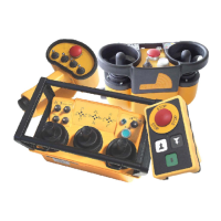
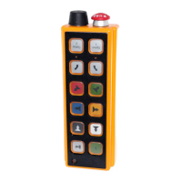
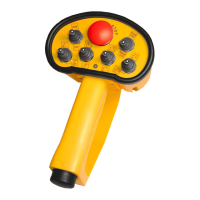
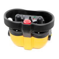
Please note that the actual configuration of each radio
remote control system is designed specifically per
customer requirements and may vary from the
illustrations shown in this manual. Refer to the
technical documentation provided with each system for
the actual design, layout and components.
The types of transmitters which can be used with the
radio remote control system are:
• Nova-M
• Nova-L
• Nova-XL
•GL
•GL-3
•GR
1
24
1
2
3
PIN
PIN
D16
A1
1
2
3
1. Connector Housing
2. Connector Module
3. Retaining Screw
24 Pin Layout
64 Pin Layout
HETRONIC TRANSMITTERS