30
SPECIFICATIONS
NOVA-M DIGITAL SYSTEM
Operating range 100 m (330 ft.) typical
Frequency range 400 - 470 MHz
Deviation +/- 2 kHz
HF output power 10 mW max.
Operating
temperature range
-25° to +70° C
(-18° F to 158° F)
Enclosures IP65 weatherproof (exceeds NEMA
12/13)
Transmitter antenna Built-in
TX Weight 1.8 lb (820 g) (incl. battery)
TX Size (L, W, H) 168 x 110 x 133 mm
6.6 x 4.3 x 5.2 inches
TX Power supply 3.6V/1200mAh NiMH rechargeable
battery pack
Operation time Up to 20 hours for CS 434, CS 447
and CS 458
Up to 18 hours for STD 402
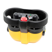
NOVA-M DIG-V04
Functions E-Stop pushbutton
Key power switch
1 Start/horn pushbutton
1 Option pushbutton
1 Three position toggle switch
2 dual axis, 360
o
control, digital two
step spring return to center
joysticks
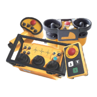
NOVA-M DIG-V05
Functions E-Stop pushbutton
Key power switch
1 Start/horn pushbutton
1 Option pushbutton
1 Three position toggle switch
1 dual axis, 360
o
control, digital
three step spring return to center
joystick
1 single axis, 360
o
control, digital
three step spring return to center
joystick
RECEIVER RX 14
Size 246 x 160 x 90 mm
9.7 x 6.3 x 3.5 inches
Weight 1690 g 3.7 lbs
Operating power 48/110/240 VAC 50/60 Hz (+/- 20%)
12/24 VDC (+/- 20%)
Current <100 mA
Safety features Self-monitoring E-Stop circuits
Fail-safe, spring forced E-Stop relay
Self-test during start-up and
operation
On-board diagnostic system with
indicators for RF communication,
power status, active outputs
Outputs 1 NO Potential-free E-Stop relay at
8A 30VDC/240VAC
14 NO Potential-free relays at 8A
30VDC/240VAC
RECEIVER RX 20-0020 & RX
20-0021
Size 246 x 160 x 90 mm (does not
include external antenna)
9.7 x 6.3 x 3.5 inches
Weight 1690 g 3.7 lbs
Operating power 48/110/240 VAC 50/60 Hz (+/- 20%)
12/24 VDC (+/- 20%)
Current <100 mA
Safety features Self-monitoring E-Stop circuits
Fail-safe, spring forced E-Stop relay
Self-test during start-up and
operation
On-board diagnostic system with
indicators for RF communication,
power status, active outputs
Outputs 1 NO Potential-free E-Stop relay at
8A 30VDC/240VAC
18 NO Potential-free relays at 8A
30VDC/240VAC
2 NO/NC Potential-free relays at 8A
30VDC/240VAC
 Loading...