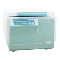
Do you have a question about the Hettich ROTINA 38 and is the answer not in the manual?
General information regarding repair authorization, spare parts, and document rights.
Explanation of warning symbols used in the repair instructions for hazard awareness.
Details the CP as the master unit, its tasks, and serial interface.
Explains the functions of the SB, including power supply and signal transmission.
Describes the FC's role in motor power generation and monitoring.
Highlights the multiprocessor concept, interface, and hardware safety features.
Details the 3-phase motor, speed sensor, and speed monitoring.
Explains the function of the imbalance detection switch and its operation.
Describes the lid locking mechanism and safety interlocks for safe operation.
Covers temperature behavior, sensor, and cooling board functions.
Explains the role of fans in cooling the refrigerant.
Procedure for aligning temperature sensor and electronics for accuracy.
Lists protective measures for mains input, motor, and cooling.
Outlines general steps for diagnosing and fixing centrifuge issues.
Lists error designations, codes, brief descriptions, and page references.
Instructions for resetting the device after a mains interruption.
Specific causes and elimination steps for various error codes (TACHO, IMBALANCE, etc.).
Describes control panel functions, initialization, and offset alignment.
Steps for initializing the frequency converter after replacement.
Guidance on setting the correct imbalance mode during initialization.
Procedure for aligning temperature sensor and CP electronics.
How to check and interrogate various centrifuge parameters.
Method for checking motor slippage during a centrifugation run.
Instructions for adjusting the contrast of the control panel display.
Procedure for adjusting the imbalance switch-off sensitivity.
Key technical data including voltage, frequency, load, and dimensions.
Steps for performing functional and safety checks after component replacement.
List of components with abbreviations, plugs, and connection details.
Table mapping components to working processes for disassembly/assembly.
Step-by-step guide for replacing the speed sensor (B3).
Procedure for replacing the motor (M1) and vibration dampers.
Instructions for removing and replacing the FC (A2).
Guidance on safely replacing EPROMs on the FC and CP.
Procedures for replacing the supply board, cooling board, and control panel.
Instructions for replacing control cables, lid locking, and brake resistor.
Steps for assembly/disassembly and shorting the mains choke coil.
Procedures for replacing the mains switch (Q1) and appliance plug (B1).
Steps for replacing the imbalance switch and motor fan (M5).
Guidance for replacing temperature sensors (B1 in chamber, B2 at condenser).
Procedures for replacing the compressor (M2) and gas filled damper.
Steps for replacing the isolating transformer (TR1) and fuse holder.
Details rotor codes, maximum speed, and control responses.
Schematic illustration of the centrifuge's cooling system.
Defines abbreviations for cable colors used in circuit diagrams.
Circuit diagrams for mains input and supply board configurations.
Detailed circuit diagram for the supply board (SB).
Diagram showing connections and component layout on the supply board.
Details signals and pin assignments on the control cable (CP-SB).
Block diagram illustrating the control panel's structure and connections.
Block diagram of the FC and signals related to the control panel.
Diagram showing external connections to the frequency converter (FC).
Circuit diagram illustrating the components and wiring of the cooling board.
Diagram showing connections and component layout on the cooling board.
| Type | Centrifuge |
|---|---|
| Max Speed | 15, 000 RPM |
| Capacity | 4 x 100 ml |
| Power Supply | 220-240 V, 50/60 Hz |
| Timer | 1-99 min, continuous |
| Noise Level | < 60 dB(A) |