56
CDR-850
6.5 ADJUSTMENT 2 (SERVO SYSTEM ADJUSTMENT)
CN102
CN102
1 : VC
2 : TESTEQRFP
3 : TE
4 : MPP
5 : MPXOUT
6 : FMOUT
CN354
1 : RF
2 : TE
3 : TEIN
4 : VC
5 : FEIN
6 : FE
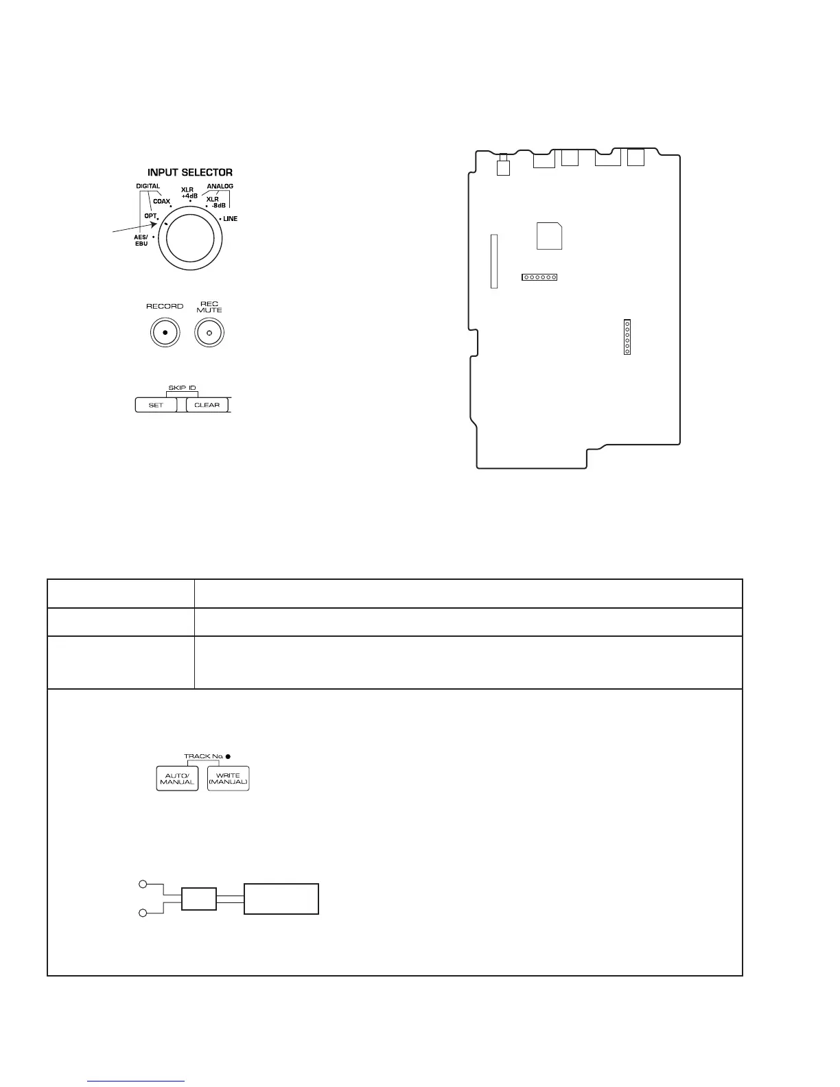
Fig. 6 Adjustment points
CN354 (TP201)
6
1
1
6
SERVO DIGITAL ASSY
For servo adjustment, set the INPUT SELECTOR to OPTICAL.
OPT
Use the RECORD and REC MUTE buttons to make the adjustments.
To reset the adjusted values to the initial settings, press and hold the
(SKIP ID) CLEAR button for 4 seconds.
To register an adjustment, press the (SKIP ID) SET button.
[Procedure]
(1) Press the AUTO/MANUAL button until "01 F4" appears on the FL display.
(2) Adjust with the RECORD and REC MUTE buttons until the value for Pin 6 of CN354 is 0 mV ± 10 mV.
(3) Press the SET button to register the adjustment.
Once the adjustment is registered with the SET button, "?" on the FL display will disappear.
6.5.1 Focus Offset Adjustment
CN354 - pin 6 (FE)
Test Point
Adjustment Point
Adjustment Value
0 mV ± 10 mV
Oscilloscope
10:1 probe
10 : 1
FE
VC
RECORD button and REC MUTE button
 Loading...