9
CDR-850
Spacer
Spacer
OK NG
A
2
1
2.8mm
11mm
Disc table Assy
(Pressure of about 9kg)
Carriage
Base
PCB
Stopper
Spindle
motor
Spacer setting
Position
Spacer
Servo Base
A
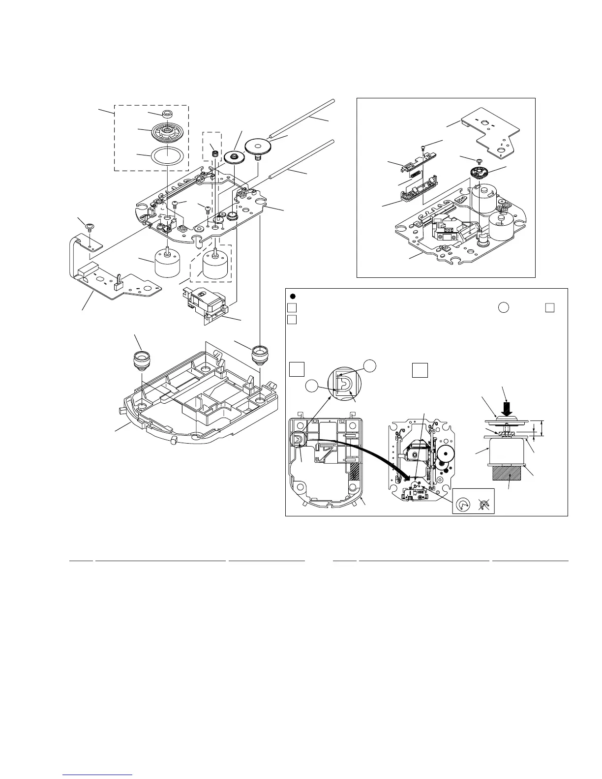
How to Install the Disc Table
1
Use nippers or other tool to cut the two sections marked
A
in figure
1
.
2
While supporting the spindle motor shaft with the stopper, put spacer on
top of the carriage base, and stick the disc table on top (takes about 9kg
pressure). Take off the spacer.
11
21
5
8
18
19
16
20
15
7
2
25
22
3
23
1
26
4
9
10
24
12
14
22
6
SERVO MECH ASSY
Carriage Base S
13
• Bottom View
•
SERVO MECHANISM ASSY PARTS LIST
Mark No. Description Part No. Mark No. Description Part No.
2.5 SERVO MECHANISM ASSY
NSP 1 SERVO MECH Assy PWZ3758
2 D.C.mortor Assy PEA1235
NSP 3 DC Motor PXM1042
4 Float Rubber A AEB7063
5 Float Rubber B AEB7066
NSP 6 Rack Spring DBH1285
NSP 7 Mirror Sheet PNM1325
8 Servo Base PNW2853
9 Pinion Gear PNW2854
10 Gear A PNW2855
11 Gear B PNW2856
12 Gear C PNW2857
13 Rack PNW2858
14 Rack Stopper PNW2859
NSP 15 Disc Table PNW2860
16 Carriage Base S PNW2874
17 • • • • •
18 Guide Bar VLL1488
19 Sub Guide Bar VLL1489
NSP 20 Magnet VYM1024
21 CD-R Pickup PEA1351
22 Screw IPZ20P060FMC
23 Screw PMZ20P030FMC
24 Screw JGZ17P030FMC
25 Disc Table Assy PEA1349
26 Carriage Motor Assy PEA1350
 Loading...