7
Radome Design Guidelines
7.1
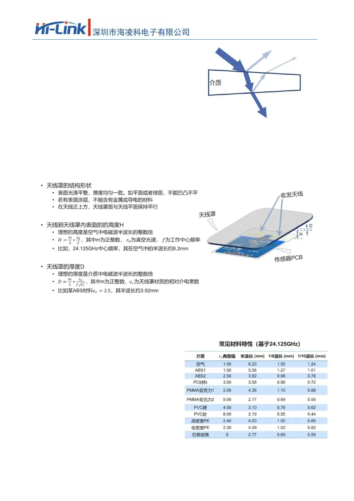
Effects of radomes on mmWave sensor performance
• Radar waves are reflected at the radome boundary
• Losses in total radar radiated or received power
• The reflected wave enters the receiving channel, affecting the isolation between the transmitting and receiving
channels
• Reflections may degrade the standing wave of the antenna, further affecting the antenna gain
• Radar waves will suffer loss when propagated in the medium. In theory, the higher the frequency, the greater
the loss will be
• Electromagnetic waves undergo a certain degree of refraction as they pass through a medium
• Affects the antenna's radiation pattern, which in turn affects the sensor's coverage
7.2
Radome Design Principles
7.3
Common materials
• Know the material and electrical
properties of the radome before
designing
• The table on the right is for reference
only, please confirm the actual value with
the supplier
• Height H from the antenna to the inner
surface of the radome
• When space permits, 1x or 1.5x
wavelength is preferred
• For example, 12.4 or 18.6mm is
recommended for 24.125GHz
• Error control: ±1.2mm
• Thickness D of the radome
• Recommended half wavelength, error
control ±20%
• If the thickness requirement at half
wavelength cannot be met
• Low er materials are recommended
• Thickness recommended 1/8
wavelength or thinner
chart
3
Common material properties of radomes
• Influence of heterogeneous materials or multi-layer composite materials on radar performance,
it is recommended to make experimental adjustments during design
 Loading...