Table of contents
1
Product introduction
........................................................................................................................
3
2
Product Features and Benefits.................................................................................................... 4
2.1 Features................................................................................................................................................... 4
2.2 Solution advantage.............................................................................................................................5
3
Application scenarios
.......................................................................................................................
6
4
Hardware Description......................................................................................................................7
4.1 Dimensions............................................................................................................................................ 7
4.2 pin definition.........................................................................................................................................7
5
use and configuration..................................................................................................................... 8
5.1 Typical Application Circuit............................................................................................................... 8
5.2 The role of configuration parameters.........................................................................................8
5.3 Visual configuration tool description......................................................................................... 9
5.4 Mounting method and sensing range......................................................................................10
5.5 Installation conditions.....................................................................................................................12
6
Performance and Electrical Parameters................................................................................13
7
Radome Design Guidelines
.........................................................................................................
14
7.1 Effects of radomes on mmWave sensor performance
.......................................................
14
7.2 Radome Design Principles
.............................................................................................................
14
7.3 Common materials
...........................................................................................................................
14
8
revision history
.................................................................................................................................
15
9
Technical Support and Contact
.................................................................................................
15
Chart Index
表 1 Pin Definition Table............................................................................................................................................................ 7
表 2 Performance and Electrical Parameters Table.......................................................................................................... 13
表 3 Common material properties of radomes.................................................................................................................14
图 1 Diagram of how to use......................................................................................................................................................3
图 2 Comparison of millimeter wave radar scheme and other schemes..................................................................... 5
图 3 Application scenarios.........................................................................................................................................................6
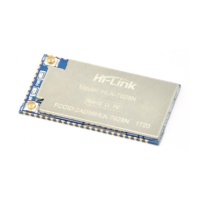
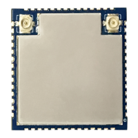
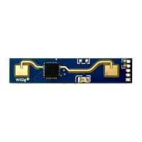
图 4 Module physical map.........................................................................................................................................................7
图 5 Module Dimensions........................................................................................................................................................... 7
图 6 Module pin definition diagram.......................................................................................................................................7
图 7 Ceiling installation diagram...........................................................................................................................................10
图 8 Schematic diagram of detection range (the ceiling height is 3 meters)...........................................................10
图 9 Wall Mounting Diagram................................................................................................................................................. 11
图 10 Schematic diagram of detection range (wall-mounted height 1.5 meters).................................................. 11
图 11 Measured data of module working current............................................................................................................13
 Loading...