Shenzhen Hi-Link Electronic Co., Ltd. Manual
Page
18
/ 19
8. Radome design guidelines
8.1
Effects of radomes on mm wave sensor performance
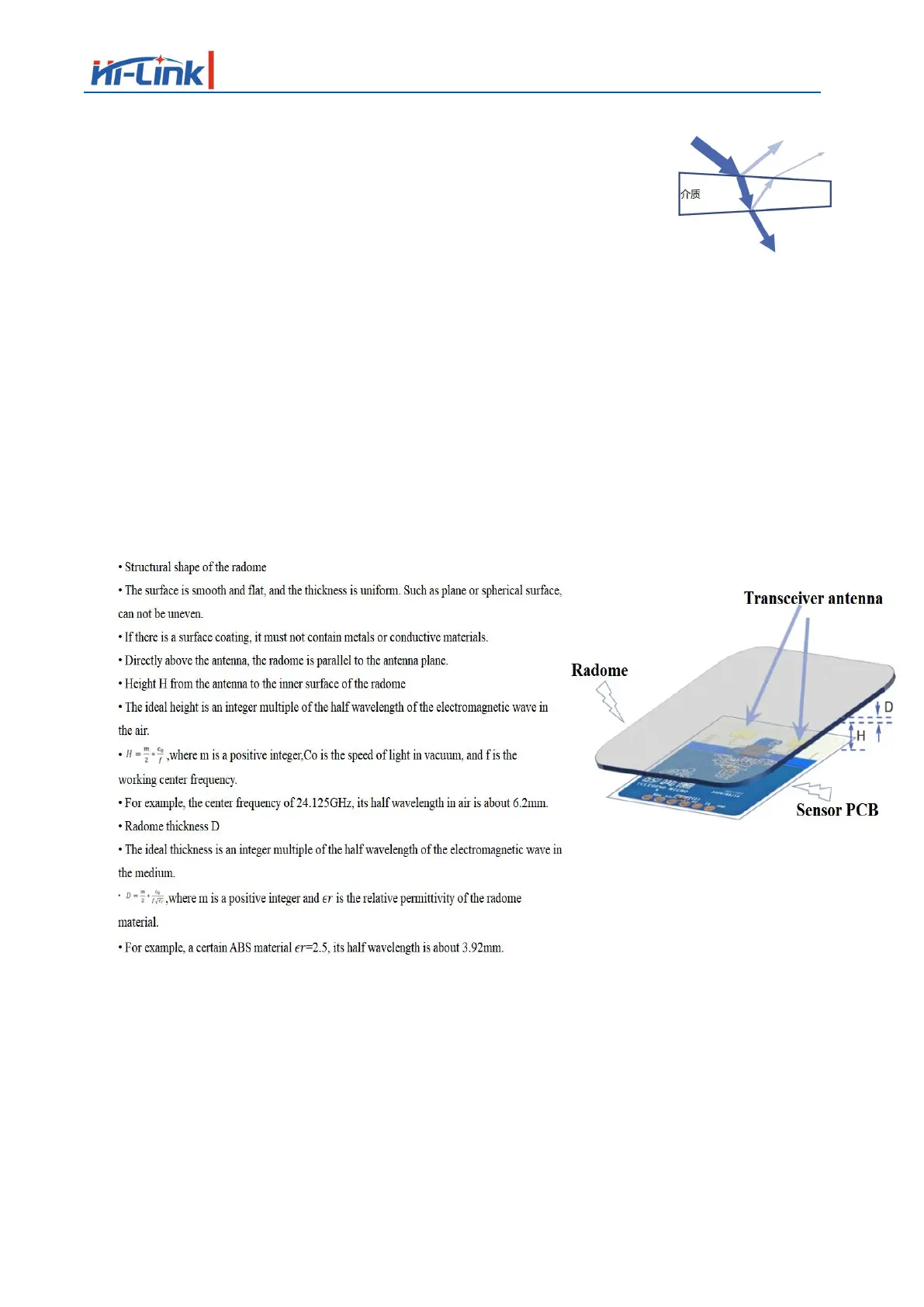
• Radar waves are reflected on the radome boundary
• Losses in total radar radiated or received power
• The reflected wave enters the receiving channel, affecting the isolation between the
transmitting and receiving channels
• Reflections may degrade the standing wave of the antenna, further affecting the antenna gain
• Radar waves will suffer loss when propagated in the medium. In theory, the higher the
frequency, the greater the loss will be
• Electromagnetic waves undergo a certain degree of refraction as they pass through a medium
• Affects the antenna's radiation pattern, which in turn affects the sensor's coverage
8.2
Radome design principles
8.3
Common materials
• Understand the material and electrical characteristics of the radome before designing
• The table on the right is for reference only, the actual value should be confirmed with the
supplier
• Height H from the antenna to the inner surface of the radome
• If there is enough space, it is preferred to recommend 1 times or 1.5 times the wavelength
• For example, 12.4 or 18.6mm is recommended for 24.125GHz
• Error control: ±1.2mm
 Loading...