RKL40, RPKL40, RKLB40
SRD MODEL: RKCL40E, RPKCL40E, RKCLB40E
iCLASS SE® Biometric/
iCLASS SE Display Reader
PLT-03331, Rev. A.2
2
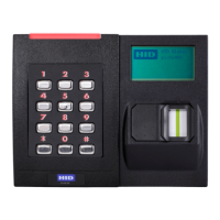
PIGTAIL TERMINAL DESCRIPTION
Yellow P1-1 Beeper Input
Orange P1-2 LED Input (GRN)
Black P1-3 Ground (RTN)
Red P1-4 +VDC
Drain P1-5 Unused
Brown P1-6 LED Input (RED)
Blue P1-7 Hold Input
Red/Green P2-7 GPIO1/OSDP (RS485-FDX/HDX-A)
Tan P2-6 GPIO2/OSDP (RS485-FDX/HDX-B)
Violet P2-5 *Open Collector Output / Tamper
White P2-4 **Wiegand Data 1 / Clock
Green P2-3 **Wiegand Data 0 / Data
Pink P2-2 GPIO3 (RS485-FDX-Z)
Gray P2-1 GPIO4 (RS485-FDX-Y)
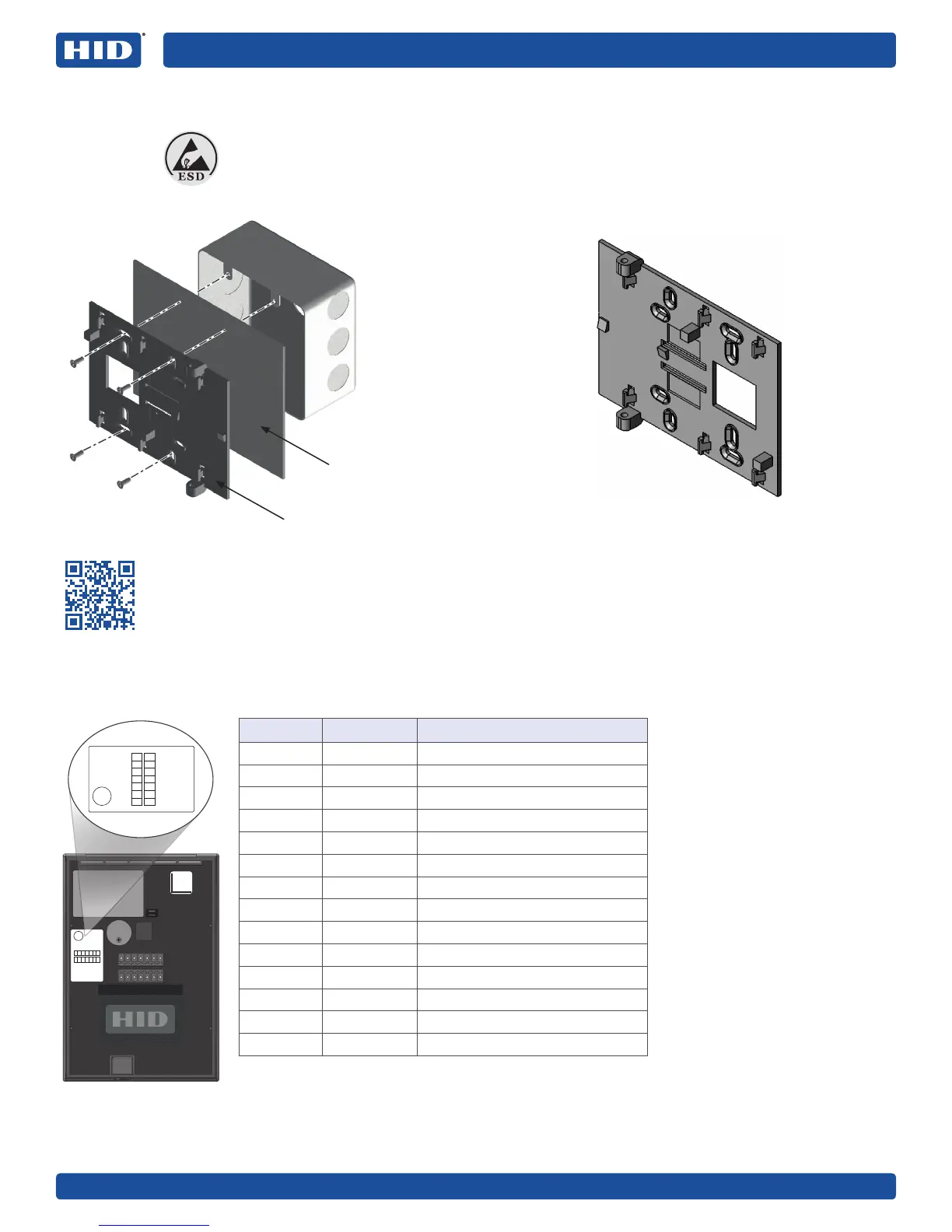
Wall backplate
Install gasket
Junction box
not included
ATTENTION
Observe precautions for handling ELECTROSTATIC SENSITIVE DEVICES
P1
P2
Beeper
GRN LED
GND
+VDC
DRAIN
RED
HOLD
GPIO1
GP102
OC/TMPR
DATA1/CLK
DATA2/DATA
GPIO3
GPIO4
Beeper
GRN LED
GND
+VDC
DRAIN
RED
HOLD
GPIO1
GP102
OC/TMPR
DATA1/CLK
DATA2/DATA
GPIO3
GPIO4
1 Mounting
2 Wiring
Mounting holes for US double-gang electrical boxes.
Terminal Reader
(Terminal block and
module position varies)
Notes
Previous iCLASS readers had
reversed RS-485 wiring (P2-7 &
P2-6 - A & B). When upgrading
to an iCLASS SE reader, ensure
proper connections as defined
below.
It is possible to reuse existing
Wiegand wiring for OSDP,
however, using simple stranded
cable typical of Wiegand
access control readers is
usually not meeting the RS485
twisted pair recommendations.
For OSDP cable lengths
greater than 200ft. (61M) or
EMF interference, install 120Ω
+/- 2Ω resistor across RS-485
termination ends.
Wiring the reader incorrectly
may permanently damage the
reader.
Reverse Configuration
Rotating the backplate 180° allows for placing the LCD display on left and the reader on right.
See PLT-02969 - Alternate Reader Assembly for instructions, before proceeding to Step 2: Wiring.
Scan the QR Code or visit www.hidglobal.com/PLT-02969