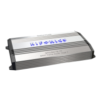
A800.4D
A1200.4D
A1000.2D
A1200.1D
A1500.1D
A2000.1D
A3000.1D
A2500.5D
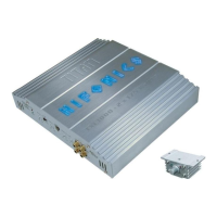
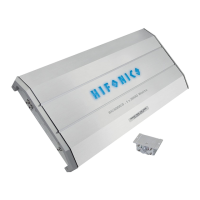
EXTERNAL
Place terminal in a secure
position so that it won’t
accidentally contact the
negative battery post
Power cable size
and fusing
It is critical to use the proper power
and ground cable. Select the size
listed here for your amplier model.
Always use high quality copper
cable. Visit our website for multi amp
system cable recommendations.
Be sure to use the proper fuse size
for each model. Some models require
an external fuse.
Properly route power,
speaker and RCA cables
through the vehicle.
Choose a mounting location
that will provide adequate air
ventilation. Mount the amplier to
a secure surface. Do not mount
the amplier upside down.
Attach the chassis ground
cable to the amplier
negative terminal. It is
important to make sure this
connection is very tight.
Bare metal
Attach the main power cable
to the amplier +12V. The
cable must run directly to
the battery and be properly
fused and be very tight.
Attach the remote turn on
wire to the amplier remote
output of the source unit.
Connect the RCA cables to
the INPUT connectors. The
OUTPUT can be used to
provide input for a second
amplier.
Connect the power cable to the
positive battery terminal. The
power cable must be fused
within 18 inches of the battery
terminal.
Re-connect the negative
battery terminal making sure it
is securely tightened.
Connect the speaker cables to
the speaker output connectors.
Follow the diagram below
that best ts your speaker
conguration.
The chassis ground connection
is critical to the performance
of the amplier. Choose a
location that is close to the
amplier. Completely scrape
away the paint and use a nut
and bolt if possible.
DO NOT USE AN EXISTING
FACTORY BOLT!
Disconnect
negative battery
terminal
Run Cables
Mount Amplier
Negative Power
Connection
Positive Power
Connection
Remote Turn-on
Connection
Signal Input
Connection
Positive Battery
Connection
Re-connect
Negative Battery
Terminal
Speaker
Connections
Chassis Ground
Be prepared to disarm your vehicle’s alarm and
to enter your radio / source unit code.
Stereo
Installation
Before you start
Monoblock
single woofer Monoblock multiple woofers
Bridged
CAUTION
Many new and factory radios require a reset code when
disconnected from battery power. This is an anti-theft
feature. Before unplugging power, you must determine if
your radio/source unit requires a reset code. Check the
operation manual for your vehicle or contact the dealer.
1
2
3
5
7
6
8
11
12
104
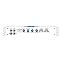
SPEAKER OUTPUT
SPEAKER OUTPUT
SPEAKER OUTPUT
SPEAKER OUTPUT
SPEAKER
LEFT
RIGHT
BRIDGED
OUTPUT
SPEAKER
LEFT RIGHT
BRIDGED
OUTPUT
SPEAKER
LEFT RIGHT
BRIDGED
OUTPUT
SPEAKER
LEFT RIGHTCH1/2 CH3/4
CH3/4
BRIDGED
OUTPUT SPEAKER
LEFT RIGHT
BRIDGED
Speakers Subwoofer
OUTPUT
SPEAKER
CH 1
CH 2
BRIDGED
CH 3
CH 4
BRIDGED
OUTPUT
SPEAKER OUTPUT
CH 3
CH 4
BRIDGED
SPEAKER OUTPUT
CH 1
CH 2
SPEAKER OUTPUT
CH 3
CH 4
SPEAKER OUTPUT
CH 5
SPEAKER
LEFT RIGHT
BRIDGED
OUTPUT
SPEAKER OUTPUT
SPEAKER OUTPUT
SPEAKER OUTPUT
SPEAKER OUTPUT
SPEAKER OUTPUT
SPEAKER OUTPUT
SPEAKER
LEFT RIGHT
BRIDGED
OUTPUT
SPEAKER
LEFT RIGHT
BRIDGED
OUTPUT
SPEAKER
LEFT
RIGHT
BRIDGED
OUTPUT
SPEAKER
LEFT RIGHTCH1/2 CH3/4
CH3/4
BRIDGED
OUTPUT SPEAKER
LEFT RIGHT
BRIDGED
Speakers Subwoofer
OUTPUT
SPEAKER
CH 1
CH 2
BRIDGED
CH 3
CH 4
BRIDGED
OUTPUT
SPEAKER OUTPUT
CH 3
CH 4
BRIDGED
SPEAKER OUTPUT
CH 1
CH 2
SPEAKER OUTPUT
CH 3
CH 4
SPEAKER OUTPUT
CH 5
SPEAKER
LEFT RIGHT
BRIDGED
OUTPUT
SPEAKER OUTPUT
SPEAKER OUTPUT
SPEAKER OUTPUT
SPEAKER OUTPUT
SPEAKER OUTPUT
SPEAKER
LEFT RIGHT
BRIDGED
OUTPUT
SPEAKER
LEFT RIGHT
BRIDGED
OUTPUT
SPEAKER
LEFT RIGHT
BRIDGED
OUTPUT
SPEAKER
LEFT RIGHTCH1/2 CH3/4
CH3/4
BRIDGED
OUTPUT SPEAKER
LEFT RIGHT
BRIDGED
Speakers Subwoofer
OUTPUT
SPEAKER
CH 1
CH 2
BRIDGED
CH 3
CH 4
BRIDGED
OUTPUT
SPEAKER OUTPUT
CH 3
CH 4
BRIDGED
SPEAKER OUTPUT
CH 1
CH 2
SPEAKER OUTPUT
CH 3
CH 4
SPEAKER OUTPUT
CH 5
SPEAKER
LEFT RIGHT
BRIDGED
OUTPUT
SPEAKER OUTPUT
SPEAKER OUTPUT
SPEAKER OUTPUT
SPEAKER OUTPUT
SPEAKER OUTPUT
SPEAKER OUTPUT
SPEAKER
LEFT RIGHT
BRIDGED
OUTPUT
SPEAKER
LEFT RIGHT
BRIDGED
OUTPUT
SPEAKER
LEFT RIGHT
BRIDGED
OUTPUT
SPEAKER
LEFT RIGHTCH1/2 CH3/4
CH3/4
BRIDGED
OUTPUT SPEAKER
LEFT RIGHT
BRIDGED
Speakers Subwoofer
OUTPUT
SPEAKER
CH 1
CH 2
BRIDGED
CH 3
CH 4
BRIDGED
OUTPUT
SPEAKER OUTPUT
CH 3
CH 4
BRIDGED
SPEAKER OUTPUT
CH 1
CH 2
SPEAKER OUTPUT
CH 3
CH 4
SPEAKER OUTPUT
CH 5
SPEAKER
LEFT RIGHT
BRIDGED
OUTPUT
SPEAKER OUTPUT
SPEAKER OUTPUT
Turn the LEVEL control completely
counter-clockwise to minimum.
Level Control
9
9V 0.2V
INPUT
LEVEL
6V 0.2V
INPUT
LEVEL
PHASE
0 180
BASS EQ
0 10dB
BASS EQ
0 9dB
BASS EQ
0 12dB
15 35Hz
SUBSONIC
10 40Hz
SUBSONIC
30 250Hz
LPF
35 250Hz
LPF
40 300Hz
LPF
FULL
LP
HP
XOVER
MONO STEREO
MODE
FULL
LPF
HPF
XOVER
MONO STEREO
MODE
4CH 2CH
MODE
60 1.3KHz
HPF
60 1.2KHz
HPF
10 2.5KHz
HPF
10 1.5KHz
HPF
Model Fuse Size Cable Size
4ga