RocketRAID 2640X4 Hardware Description/Installation
2-2
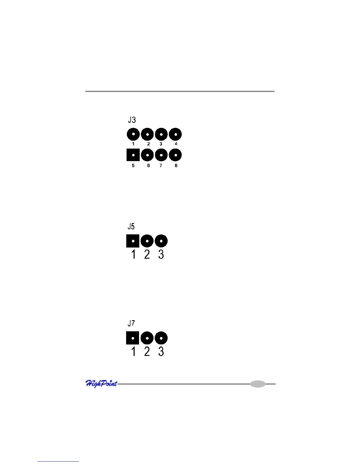
Pins defined as follows:
Pin 1: NC; Pin 2: SDATAIN; Pin 3: GND; Pin 4: SDATAOUT; Pin 5: SLOAD; Pin 6:
GND; Pin 7: SCLOCK; Pin 8: NC.
J5
These jumper can be used to select PCI-E work model. As following:
Connect Pin 1 and Pin 2 support PCI-E X1, and connect Pin 2 and Pin 3 support PCI-E
X4.
BEEP1-Speaker
Alarm (speaker): the speaker emits and audible alarm in the case of disk/array failure.
J7
This support SAF-TE interface(I2C).
J3
This jumper is SGPIO signal.The following diagram describes the connector pin
definitions.
Pins defined as follow:
Pin 1: SCL; Pin 2: GND ; Pin 3: SDA.