Quick Start Guide of Digital Video Recorder
13
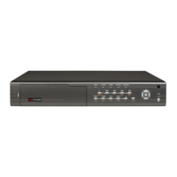
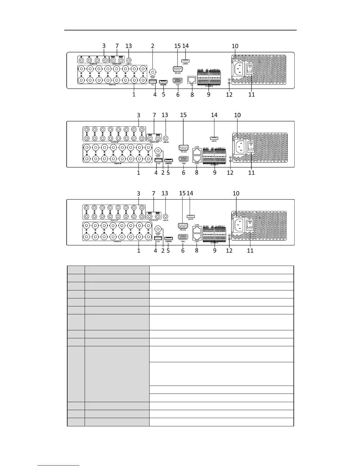
DS-7300HQHI-SH and DS-7300HGHI-SH
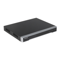
DS-8100HGHI-SH
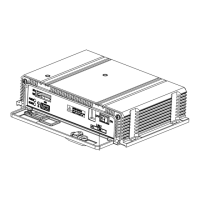
DS-8100HQHI-SH
BNC interface for TVI and analog video input.
BNC connector for video output.
Universal Serial Bus (USB) port for additional devices.
HDMI video output connector.
DB15 connector for VGA output. Display local video output and
menu.
Connector for RS-485 devices. T+ and T- pins connect to R+ and R-
pins of PTZ receiver respectively.
D+, D- pin connects to Ta, Tb pin of controller. For cascading
devices, the first DVR’s D+, D- pin should be connected with the
D+, D- pin of the next DVR.
Connector for alarm input.
Connector for alarm output.
AC 100 ~ 240V power supply.
Switch for turning on/off the device.
 Loading...