Unmanaged PoE Switch/User Manual
14
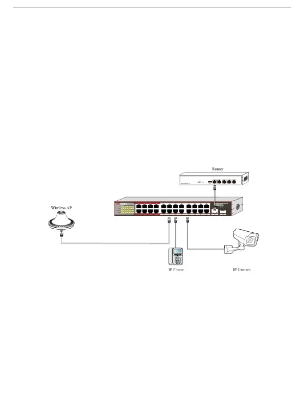
Chapter 3 Physical Connection
RJ45 Port Connection
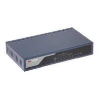
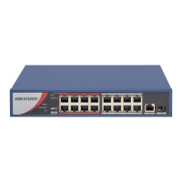
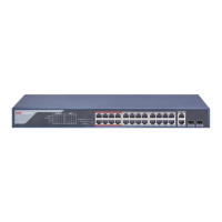
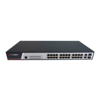
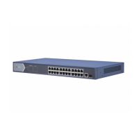
Connect the RJ45 ports of the switch to the RJ45 ports of peer devices. The ports marked with “Uplink” and “G1” are the
uplink ports, and the other ports are downlink ports. All ports of DS-3E0108P-E are ordinary RJ45 ports, not being
divided into uplink and downlink ports.
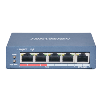
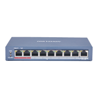
Ports 1 - 4 of DS-3E0108P-E and all downlink ports of DS-3E0109P-E/M, DS-3E0109P-E/M, and DS-3E0326P-E/M
support PoE power supply, and can provide power for IEEE 802.3af and IEEE 802.3at powered devices, such as AP, IP
phone, IP camera, and so on.
The switch supports auto MDI/MDIX. That is, you can use straight-through cable or crossover cable to connect the switch
to the peer device. CAT 5 or better Ethernet cable is recommended.
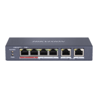
SFP Port Connection
Procedure
* Available only on DS-3E0318P-E/M and DS-3E0326P-E/M.
Step 1: Connect your optical module to the SFP port. Ensure that the direction of the optical module is correct.