EasyManua.ls Logo

HIKVISION DS-KD-M User Manual

HIKVISION DS-KD-M
98 pages
To Next Page IconTo Next Page
Page #1 background imageLoading...
Page #1 background image
Module Door Staon
User Manual
UD30508B

Table of Contents

Other manuals for HIKVISION DS-KD-M

Question and Answer IconNeed help?

Do you have a question about the HIKVISION DS-KD-M and is the answer not in the manual?

HIKVISION DS-KD-M Specifications

General IconGeneral
Product typeCard reader
Mounting typeSurface
Product colorBlack
Brand compatibilityHikvision
International Protection (IP) codeIP65
Package weight421 g
Quantity per pack1 pc(s)
Storage temperature (T-T)10 - 95 °C
Operating temperature (T-T)-40 - 55 °C
DC input voltage12 V
Sustainability certificatesREACH, RoHS, WEEE
Weight and Dimensions IconWeight and Dimensions
Depth33.7 mm
Width98.5 mm
Height100 mm
Weight160 g

Summary

Legal Information

About this Manual

Provides an overview of the manual's content and purpose.

Trademarks

Lists Hikvision's trademarks and acknowledges others.

Disclaimer

Outlines limitations of liability, warranty, and user responsibilities.

Data Protection

Symbol Conventions

Regulatory Information

FCC Information

Provides compliance details for FCC regulations.

FCC Conditions

Specifies the two conditions under which the device complies with FCC rules.

EU Conformity Statement

States compliance with European Union directives.

Industry Canada ICES-003 Compliance

1 Introduction

2 Appearance

Main Unit

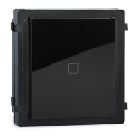
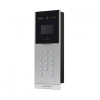
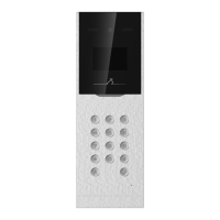
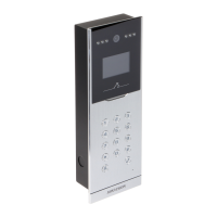
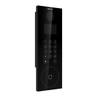
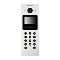
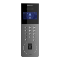
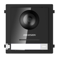
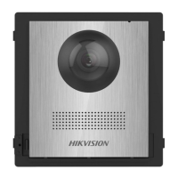
Details the appearance and components of the main unit.

Two-Wire Main Unit

Nametag Module

Keypad Module

Indicator Module

PMR Indicator Module

Card Reader Module

Display Module

Information Module

Touch-Display Module

3 Terminal and Wiring

3.1 Terminal Description

Details the terminals and interfaces of the main unit.

Main Unit Terminals

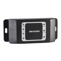
Illustrates and describes the terminals on the main unit.

Two-Wire Main Unit Terminal

Sub Module Terminal (Except Touch-Display Module)

Touch-Display Module

3.2 Module Door Station Wiring

3.2.1 Door Lock Wiring

Details the wiring for connecting door locks.

3.2.2 Door Contact Wiring

3.2.3 Exit Button Wiring

3.2.4 RS-485 Card Reader Wiring

4 Installation

4.1 Configure Sub Module Address

Explains how to set the sub module address using DIP switches.

4.2 Two-Module Installation

4.2.1 Two-Module Surface Mounting

Guides on surface mounting for two-module setups.

4.2.2 Two-Module Flush Mounting

4.3 Three-Module Installation

4.3.1 Three-Module Surface Installation

Details surface mounting for three-module setups.

4.3.2 Three-Module Flush Mounting

4.4 More-Than-Three Module Installation

4.4.1 More-than-Three Module Surface Mounting

Details surface mounting for configurations exceeding three modules.

4.4.2 More-Than-Three Module Flush Mounting

5 Activation

5.1 Activate Device via Client Software

Guides activation using the client software.

5.2 Edit Network Parameters

6 Remote Configuration via Web

6.1 Live View

Describes how to access and view live video feeds.

6.2 User Management

6.3 Device Management

6.4 Remote Configuration

6.4.1 Local Parameters Settings

Configures local parameters for live view, records, and pictures.

6.4.2 System Settings

Maintenance

Authentication

Security Service

User Management

Online Users

Arming/Disarming Information

6.4.3 Network Settings

6.4.4 Video & Audio Settings

6.4.5 Image Settings

OSD Settings

Target Cropping

6.4.6 Event Settings

Motion Detection

Sets up motion detection areas, sensitivity, and actions.

Event Linkage

6.4.7 Schedule Settings

Schedule Settings

Sets up weekly and holiday schedules for device operation.

6.4.8 Intercom Settings

Sub Module Configuration

Number Settings

7.3.9 Access Control Settings

Door Parameters

Sets parameters for linked doors, including open duration and relay reverse.

Elevator Control

6.4.10 Theme Settings

7 Configuration via Client Software

7.1 Device Management

Covers activating, adding, editing, and deleting devices in the client software.

7.1.2 Add Device by IP Address

7.1.3 Add Device by IP Segment

7.2 Live View via Door Station

7.3 Remote Configuration

7.3.1 Device Management

Manages linked devices through the client software.

7.3.2 Local Parameters Settings

7.3.3 System Settings

Authentication

Security Service

User Management

Online Users

Arming/Disarming Information

7.3.4 Network Settings

7.3.5 Video & Audio Settings

7.3.6 Image Settings

OSD Settings

Target Cropping

7.3.7 Schedule Settings

Schedule Settings

Sets up weekly and holiday schedules for device operation.

7.3.8 Intercom Settings

Press Button to Call

Input and Output

Sub Module Configuration

Number Settings

7.3.9 Access Control Settings

Permission Password

Sets up passwords for access control permissions.

Door Parameters

Card Security

Elevator Control

7.4 Organization Management

7.4.1 Add Organization

Guides the process of adding new organizations.

7.4.2 Modify and Delete Organization

7.5 Person Management

7.5.1 Add Person

Guides the process of adding person details and photos.

7.5.2 Modify and Delete Person

7.5.3 Import and Export Person Information

7.5.4 Get Person Information from Device

7.5.5 Change Person to Other Organization

7.5.6 Issue Card in Batch

8 Video Intercom Operation

8.1 Video Intercom Operation via Device

Details video intercom operations performed directly on the device.

8.1.1 Call Resident

8.1.2 Issue Card

8.1.3 Unlock Door

8.2 Video Intercom Operation via Client Software

8.2.1 Receive Call from Door Station

Guides receiving calls from the door station via the client software.

8.2.2 Live View via Door Station

8.2.3 View Call Logs

8.2.4 Search Video Intercom Information

A. Relevant Instructions for External Power Supply and Wiring of 2-wire Video Intercom Products (2020-1-20)

Power Description

Details power consumption of distributors and door station modules.

Example of the Calculation Model of the Modular Door Station Sub-Module

Wire Testing Standards

Device Installation

B. Communication Matrix and Device Command

Communication Matrix

QR code to access the device communication matrix.

Device Command

QR code to access device serial port commands.

Related product manuals