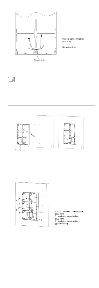
Figure 4-33 Place the Grounding Line and Module-Connecng
Line
Note
●
There are 6 module-connecng lines in the package: 190
mm × 4 and 400 mm × 2.
●
Take the 400 mm module-connecng line for this step.
●
The green-yellow line in the package is for grounding.
6. Fix the mounng frame onto the wall with 8 expansion bolts.
Figure 4-34 Fix the Mounng Frame
7. Pass the main unit connecng line across the thread hole to
the top grid of the le frame. Thread the module-connecng
line (190 mm) across the thread hole of the frame. The lines
should be placed as shown below.
Figure 4-35 Placement of Lines
8. Connect the cables.
1) Connect the cables from the wall and module-connecng
line 1 to the corresponding interfaces of the main unit, then
place the main unit into the upper grid.
27
 Loading...