2
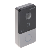
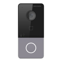
DS-KV61X3-(W)PE1
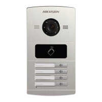
Video Intercom Villa Door Staon UD20195B-B
Microphone
2
Indicator
3
Buon
4
Card Reading Area
5
Loudspeaker
6
Terminals
7
Debugging Port
8
Note: The debugging port is used for debugging only.
Terminal and Wiring
2
Installaon Accessory
3
ENGLISH
Diagram References
Appearance
1
Surface Mounng without Protecve Shield
1. Sck the mounng template on the wall. Drill screw holes according to the mounng
template. Remove the template from the wall.
2. Secure the mounng plate on the wall with 4 supplied screws according to the screw
holes.
3. Install the villa door staon to the mounng plate. Fix the device on the mounng
plate with the set screw.
Surface Mounng with Protecve Shield
Make sure all related equipments are power-off during the installaon.
Tools that you need to prepare for installaon:
Drill (ø2.846) and gradienter.
Purchase the protecve shield before installaon.
Before You Start
1. Sck the mounng template on the wall. Drill the screw holes according to the
mounng template. Remove the template from the wall.
2. Align the protecve shield with the mounng template.
3. Secure the mounng plate and protecve shield on the wall with 4 supplied screws
according to the screw holes.
4. Install the villa door staon to the mounng plate. Fix the device on the mounng
plate with the set screw.
11
Configuraon via Web
5
You are required to acvate the device first by sengs a strong password before you
can use the device.
Acvate Device via Web
1
Access to the Device by Web Browsers
2
1. In the browser address bar, enter the IP address of the device, and press the Enter
key to enter the login page.
2. Enter the user name and password and click Login.
Refers to Video Intercom Villa Door Staon User Manual (scan the QR code) for details.
1
TAMPER
9
4
2
3
4
5
6
7
8
9
10
11
12
Exit Button
TO EXIT
2
1
3
ScrewsScrew
Villa Door Station
Mounting Plate Mounting Template Wall
1
3
4
2
Screws
Screws
Screw
Villa Door Station
Mounting Plate Protective Shield Mounting Template Wall
The re comme nded distan ce from t he grou nd level is 1.4 0
adju stabl e depends on th e heigh t of body.
102023104
Hole1
Hole2
Hole1
Hole1 Hole1
102.58
1.18
Unit : mm
6.2
39.24
3.45
3
Orange RS-485+
Yellow RS-485-
Red 12 VDC
Black GND
White AIN1
White AIN2
White AIN3
White AIN4
Yellow NC
Green COM
Blue NO
Black GND
Black GND
PRESS
Power
Input
Reserved
1
2
Surface Mounng without Protecve Shield
Surface Mounng with Protecve Shield
DS-KV6103-PE1 DS-KV6113-WPE1
1
Camera
Set Screw
10
TF Card Slot
11
Network Interface
12
Indicator Descripon
Unlock: Green Call: Orange Communicate: White
NC: Door Lock Relay Output (NC)
NO: Door Lock Relay Output (NO)
COM: Common Interface
AIN1: For the access of Door Contact
AIN3: For the access of Exit Buon
AIN2&AIN4: Reserved
485-: RS-485 Interface (Reserved)
485+: RS-485 Interface (Reserved)
12 VDC IN: Power Supply Input
GND: Grounding
Mounng Template
2
1
Mounng Plate
Note: The dimension of the mounng plate is 102.58 mm × 39.24 mm × 6.2 mm.
Installaon
4
Note: Video intercom villa door staon supports surface mounng.
Default parameters of door staon are as follows:
Default IP Address: 192.0.0.65.
Default Port No.:8000.
Default User Name: admin
1. Power on the device, and connect the device to the network.
2. Enter the IP address into the address bar of the web browser, and click Enter to enter
the acvaon page.
Note: The computer and the device should belongs to the same subnet.
3. Create and enter a password into the password field.
4. Confirm the password.
5. Click OK to acvate the device.
Note: When the device is not acvated, the basic operaon and remote configuraon of device cannot be
performed.
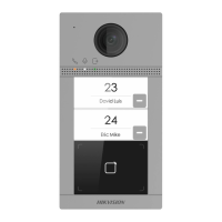
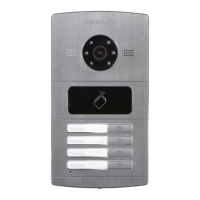
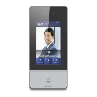
Communicate with Indoor Staon
3
1. Click Sengs -> Intercom -> Press Buon to Call to enter the sengs page.
2. Set the parameters.
- Edit call No. for every buon.
- Check Call Management Center to set the buon calling center.
Note: If you check Call Management Center and set the call No. as well, call management center has
higher privilege than call No.
3. Press buon to call indoor staon.
Issue Card
4
1. Click Sengs -> Access Control and Elevator Control to enter the sengs page.
2. Click Issue Card. Present the card on the card reading area.
3. When issuing finished, the windows pop up on the sengs page.
Note:
Only Mifare card supported, and Mifare card with non-standard shape is recommended.
Up to 10000 cards can be issued and managed by V series door staon. A voice prompt (No more cards
can be issued.) can be heard when the issued card amount exceeds the upper limit.
Unlock Door
5
Aer issuing cards, you can unlock the door by presenng the issued cards.
Model
Received frequency
Transmied frequency
Bandwidth
Frequency power
802.11b:16dBm +/- 1.5dBm
802.11g:15dBm +/- 1.5dBm
802.11n(ht20):14dBm +/- 1.5dBm
802.11n(ht40):12dBm +/- 1.5dBm
DS-KV6113-
WPE1
2.4 to 2.4835GHz
2.4 to 2.4835GHz
20 to 40MHz
Industry Canada ICES-003 Compliance
This device meets the CAN ICES-3 (B)/NMB-3(B) standards requirements.
For RED-Direcve 2014/53/EU
The frequency, mode and the maximum transmied power in EU are listed below:
The simplified declaration of conformity
Hereby, Hangzhou Hikvision Digital Technology Co., Ltd. ("Hikvision") declares that
the DS-KV6113-WPE1 device complies with the requirements of Directive 2014/53 / EU of
the European Parliament and of the Council of April 16, 2014 on the harmonization of
the laws of the Member States relating to making radio equipment available on the
market and repealing Directive 1999/5 / EC. The full text of the declaration of
conformity is available at the Hikvision website hp://www.hikvisioneurope.com/portal