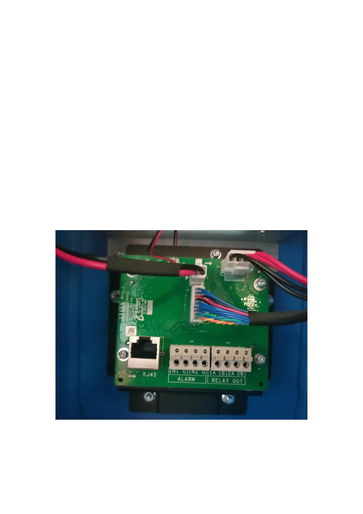
IO trigger: the trigger device is connected to IN1 and G of the ALARM port;
(2) Gate control and gate signal wiring:
Control gate: the corresponding 1A1B2A2B corresponding to the opening and
closing of the gate
The wiring of the remote control alarm signal of the gate: the output of the gate is
opened in place (remote control alarm) and connected to the camera ALARM IN1,
G
After the gate signal wiring is completed, you need to configure the relevant functions
in the Device Configuration - Entrances and Exits - Entrance and Exit - Barrier
Status - IO associated with the barrier, as shown in the following figure. In addition,
the network interface of the device can be accessed from the reserved network port on
the patch panel, and other network ports in the device are not allowed to be wired
additionally.
4. Upgrade FW
After the upgrade is successful, you will be prompted to restart, first choose not to