KB88113 Vandal-Resistant Video Intercom Doorbell User Manual
UM KB8113 Doorbell 021821NA 2
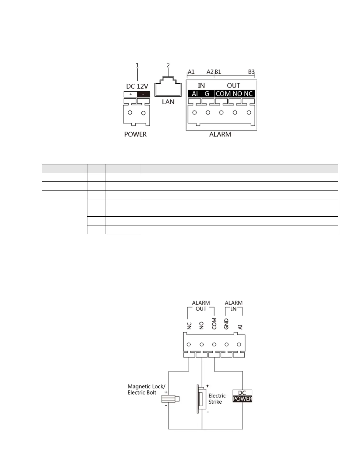
2.0 Terminal and Wiring Description
2.1 Terminals Description
Figure 2-1 Terminals Description
Table 2-1 Description
12 VDC Power Supply Input
Network Interface (PoE Supported)
ALARM IN
ALARM OUT
Door Lock Relay Output (Connect Electric Strike)
Door Lock Relay Output (Connect Electric Bolt or Contact Lock)
2.2 Wiring Description
2.2.1 Door Lock Wiring
Terminal NC/COM is set as default for connecting magnetic lock/electric bolt; terminal NO/COM is
set as default for connecting electric strike.
Figure 2-2 Door Lock Wiring