4.11 Hilow Motor
Chapter 4: Removal, Replacement, and Adjustment Procedures
4
Hill-Rom® Basic Care™ Bed, Hill-Rom® 305 Manual Bed, Page 4 - 25
Hill-Rom® 405 Electric Bed Service Manual (MAN336 REV 2)
4.11 Hilow Motor
Tools required: 10 mm hex wrench
13 mm socket
Needle nose pliers
Wire cutters
Bed supports
Removal
Do not work under an unsupported load. Install appropriate temporary
supports. Failure to do so could cause injury or equipment damage.
1. Put bed supports under the upper bed frame.
2. Disconnect the battery cable from the control board (refer to procedure 4.7
on page 4-16).
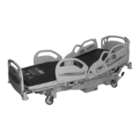
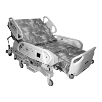
3. Raise the head section (A) to its highest position (see figure 4-11 on page
4-26).
Disconnect the bed from its power source. Failure to do so could cause
injury or equipment damage.
4. Disconnect the bed from its power source.
5. Make a note that shows how the cable routes from the hilow motor (B) to
the control box assembly (C).
Use caution when you cut the wire ties. Failure to do so could cause
cable damage.
6. Carefully cut all of the wires ties that attach the hilow motor cable (D) to
the bed frame (E).
7. Disconnect the hilow motor cable (D) from the control box assembly (C).