54
Installation RS20/22/30/32/40
Release
05
12/2015
RPS90/48V HV: connecting the input voltage
With the RPS90/48V HV high-voltage PoE power unit, you connect either
a DC or AC supply voltage at the input connection:
60 V DC to 250 V DC
110 V AC to 230 V AC
The supply voltage is connected via pin 2 and pin 3, and the protective
conductor is connected via pin 1.
First connect the protective conductor to the protective conductor
terminal.
Connect the supply voltage via the 3-pin terminal block. Pay attention
to the +/L and -/N connections.
If the neutral conductor or the minus terminal of the supply voltage is
not grounded, install a suitable fuse in the input line.
For supply voltages > 125 V DC:
Install a suitable external fuse in the supply voltage input line of the
plus terminal.
Use a supply cable with a maximum length of 2 meters to the power
unit.
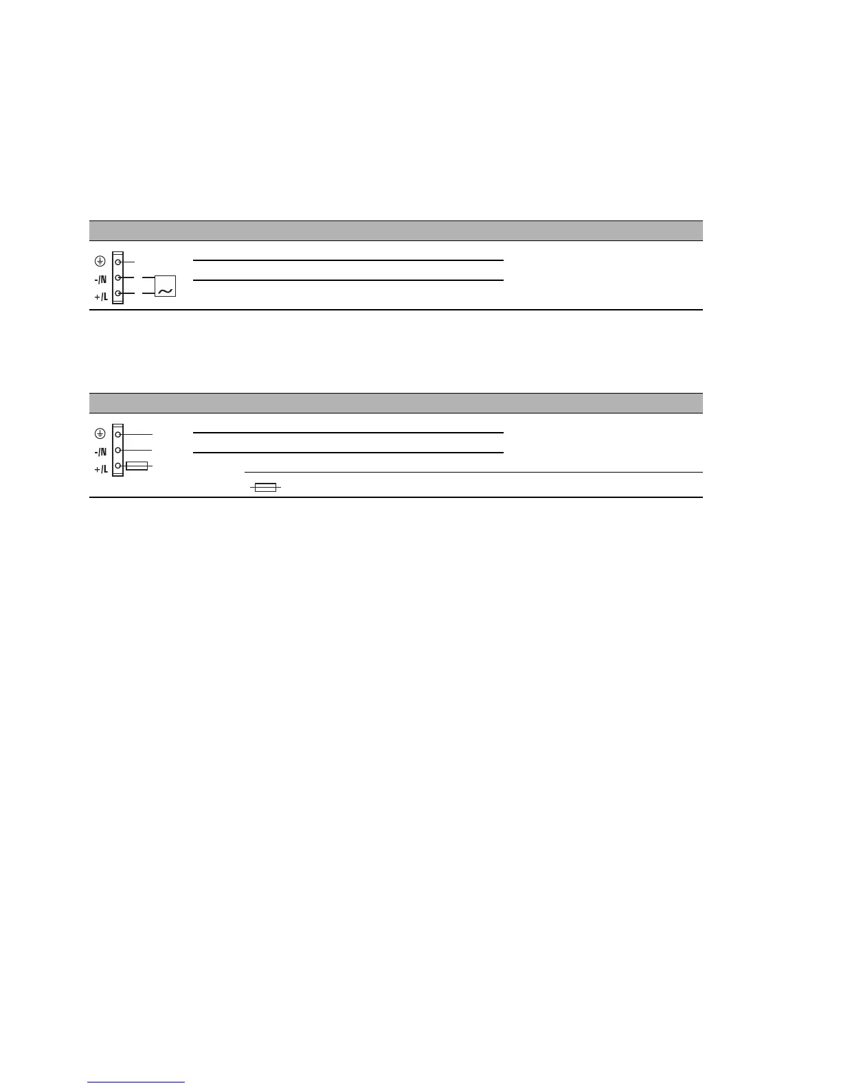
Figure Pin Assignment Supply voltage range
1 Protective conductor High voltage input voltage:
110 V AC to 230 V AC
2 Minus terminal of the supply voltage
3 Plus terminal of the supply voltage
Table 13: Connecting the high-voltage supply voltage at PoE power unit
RPS90/48V HV (AC voltage)
Figure Pin Assignment Supply voltage range
1 Protective conductor High-voltage input voltage: 60
V DC to 250 V DC
2 Minus terminal of the supply voltage
3 Plus terminal of the supply voltage
= external fuse for supply voltages > 125 V DC
Table 14: Connecting the high-voltage supply voltage at PoE power unit
RPS90/48V HV (DC voltage)
 Loading...