6
– Voltage supply: The supply voltage is
electrically isolated from the housing.
– Ground connection: The SPIDER is
grounded via a pin of the 3pin terminal
block.
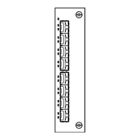
Fig. 3: Pin configuration of 3pin terminal
block
2. Configuration
2.1 CONNECTING DTE AND OTHER
NETWORK SEGMENTS
It is possible to connect with
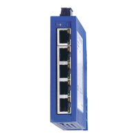
– SPIDER 3TX-TAP up to three
– SPIDER 5TX, SPIDER 5TX EEC up to five
– SPIDER 8TX, SPIDER 8TX EEC up to eight
– SPIDER 1TX/1FX... up to one
– SPIDER 4TX/1FX... up to four
data terminal equipments (DTE) or other
network segments to the 10/100 Mbit/s
ports using twisted pair cabling (ref. Fig. 4).
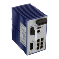
One further data terminal equipment or
optical network component can be connec-
ted at 100 Mbit/s to the optical port of the
– SPIDER 1TX/1FX...
– SPIDER 4TX/1FX...
using fiber optic cable.
3. Assembly, startup procedure
and dismantling
3.1 UNPACKING, CHECKING
䡺 Check whether the package was deliver-
ed complete (see scope of delivery).
䡺 Check the individual parts for transport
damage.
z
Warning!
Use only undamaged parts!
3.2 ASSEMBLY
The equipment is delivered in a ready-to-
operate condition. The following procedure
is appropriate for assembly:
+24 V
0 V
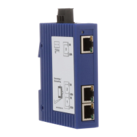
䡺 Pull the terminal block off the SPIDER
and wire up the supply voltage lines.
䡺 Fit the SPIDER on a 35 mm standard bar
to DIN EN 50 022.
䡺 Attach the upper snap-on slide bar of
the SPIDER to the standard bar and press it
down until it locks in position.
䡺 Fit the signal lines.
Notes:
– The SPIDER is grounded via a pin of the
terminal block.
– Do not open the housing.
– The shielding ground of the twisted pair
lines which can be connected is electrical-
ly connected to the ground connection.
Fig. 5: Assembling the SPIDER
Fig. 6: Dimensions
13,7
70
63,3 23
8,5
3.3 STARTUP PROCEDURE
䡺 You start up the SPIDER by connecting
the supply voltage via the 3-pin terminal
block.
3.4 DISMANTLING
䡺 To take the SPIDER off the ISO/DIN rail,
unlock the snap-in mechanism according to
Fig 7.
Fig. 7: Dismantling the SPIDER
4. Further support
In the event of technical queries, please talk
to the Hirschmann contract partner respon-
sible for looking after your account or
directly to the Hirschmann office. You can
find the addresses of our contract partners
– on the Internet
http://www.hirschmann-ac.com
Our support line is also at your disposal:
Tel. +49(1805) 14-1538
Fax +49(7127) 14-1551
Answers to Frequently Asked Questions can
be found on the Hirschmann product site
http://www.hirschmann-ac.com
The FAQs are located under „Service“ in
the Automation and Network Solutions
section.
www.hicomcenter.com gives you an up-to-
date overview of training courses about
technology and products.
MICE
SPIDER
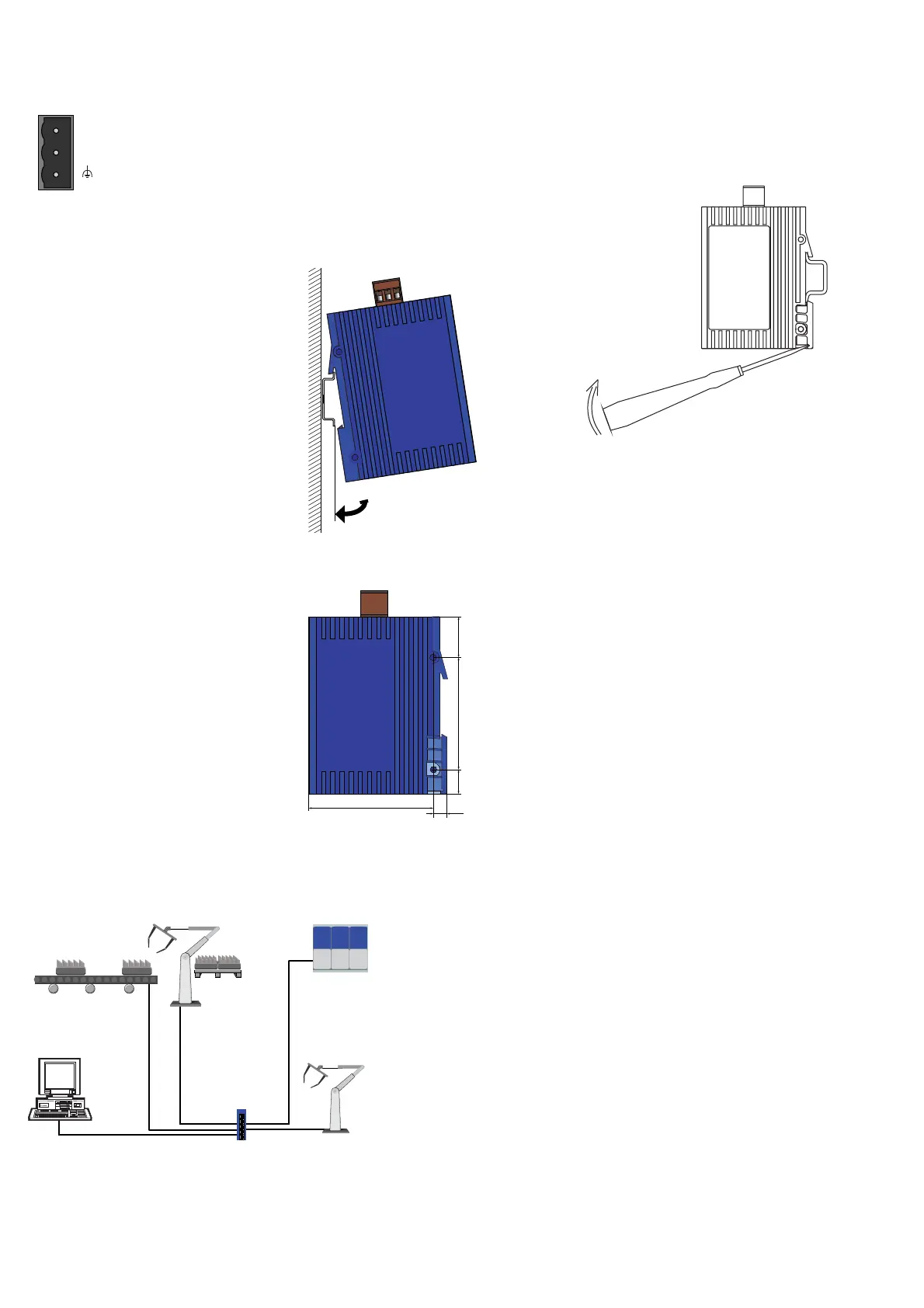
Fig. 4: Configuration with SPIDER: Connection of (depending on product type):
– up to 8 data terminal equipments or further segments via TP
– and up to 1 data terminal equipment or further segment via F/O