Do you have a question about the Hirschmann GREYHOUND GRS1020 and is the answer not in the manual?
General safety guidelines for operating the device with electricity, emphasizing proper handling and safety.
Defines characteristics of qualified personnel for safe device operation and safety technology.
Guidelines for using the device only for specified purposes with manufacturer-approved components.
Requirement to verify electrical installation compliance with local/national safety regulations.
Lists manuals and software for device operation, configuration, and monitoring.
Explains symbols used in the manual for listing, work steps, and subheadings.
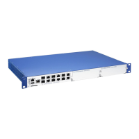
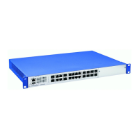
Overview of GREYHOUND devices, features, installation options, and connection media.
Explains how device names correspond to product codes and defines characteristic values.
Details how different characteristic values combine to define specific product configurations.
Illustrates and labels components on the front panel of the GREYHOUND device variants.
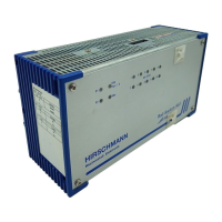
Illustrates and labels components on the rear panel of the GREYHOUND device variants.
Describes the 2-pin terminal block for power supply with characteristic value C.
Describes the 3-pin terminal block for power supply with characteristic value M.
Details the 4 combo ports supporting up to 1000 Mbit/s and connection options.
Describes the RJ45 socket for 10/100 Mbit/s connections and its features.
Details the SFP slot for 100 Mbit/s fiber optic connections and supported modes.
Explains LEDs on the device that provide information about its operational status.
Describes LEDs indicating link status, activity, and port status for network connections.
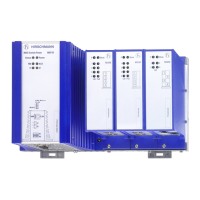
Explains the LED on the media module that indicates its power supply status.
Details the serial RJ45 socket for external management via VT100 terminal or PC.
Describes the USB interface for connecting AutoConfiguration Adapter for data and software management.
Explains the potential-free relay contact for remote diagnosis and external device control.
Instructions for verifying all items are present and checking for transport damage.
Safety warnings and initial steps for installing and grounding the device in a cabinet.
Guidelines for mounting the device in a 19" switch cabinet using rails, ensuring ventilation.
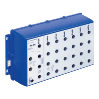
Instructions and safety warnings for mounting the device on a vertical flat surface.
Details how to ground the device, especially for variants with characteristic value M.
Step-by-step guide for inserting an SFP transceiver into the device slot.
Instructions for connecting power supply using the 2-pin terminal block for characteristic value C.
Instructions for connecting power supply using the 3-pin terminal block for characteristic value M.
Instructions for connecting the signal contact wires to the terminal block.
Procedure for installing a media module into the device slot.
Notes on torque for terminal blocks and enabling the supply voltage.
Recommendations for connecting data cables in environments with high electrical interference.
Guidance on using the inscription field for MAC address to identify the device.
Overview of default IP address, management logins, and port configurations.
Safety warnings and steps for detaching the device from its mounting.
Procedure for safely removing an SFP transceiver from its slot.
Steps for demounting a media module from the device.
Lists dimensions, weight, and power supply specifications for different GREYHOUND device variants.
Specifies operating temperature, humidity, and air pressure requirements for the device.
Details standards for radiated and conducted emissions for various applications.
Details immunity levels for electrostatic discharge, electromagnetic fields, transients, surges, and disturbances.
Covers vibration, shock, and pulse magnetic field resistance for different environments.
Lists specifications for Gigabit Ethernet SFP transceivers, including fiber types and ranges.
Lists specifications for bidirectional Gigabit Ethernet SFP transceivers.
Lists specifications for Fast Ethernet SFP transceivers.
Provides power consumption and output data for device variants and media modules.
Lists recommended accessories, including SFP transceivers and adapters.
| Operating Temperature | -40°C to +70°C |
|---|---|
| Switching Technology | Store-and-Forward |
| Storage Temperature | -40°C to +85°C |
| Humidity | 5% to 95% (non-condensing) |
| Device Type | Managed Ethernet Switch |
| Port Type and Speed | 10/100/1000BASE-TX, 100/1000BASE-X SFP |
| Power Supply | Redundant |
| Mounting Type | DIN Rail |
| Protocol Support | Ethernet/IP, Modbus TCP, PROFINET |
| MAC Address Table | 8K entries |
| Weight | 1 kg |