16
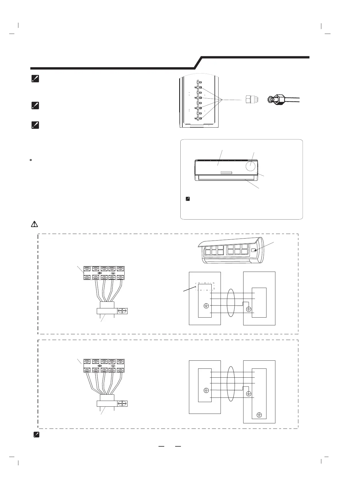
4. Connecting of the Cable
Indoor Unit
Connect the connecting cable to the outdoor unit
by connecting the wires to the terminals on the control
board individually in accordance with the outdoor unit
connection.
Note: For some models, it is necessary to remove the
cabinet to connect to indoor unit terminal.
Installation instructions
Indoor unit
Outdoor unit
1(L)
1(L)
2(N)
2(N)
4(SI)
4(SI)
3
0(L)
Connecting
cable to outdoor unit
Terminal
1
(
L)
2(
N)
3
4
(
SI)
0
(L)
Indoor unit
Outdoor unit
1(L)
1(L)
2(N)
2(N)
4(SI)
4(SI)
3
0(L)
Connecting
cable to outdoor unit
Terminal
1(
L
)
2(N
)
3
4(S
I)
0(
L)
0(L)
For the mono split
L
N
The figures in this manual are based on the external
view of a standard model. Consequently, the shape
may differ from that of the air conditioner you have
selected.
Chassis
Cabinet
Front panel
Terminal (inside)
Indoor unit
optional
The 18k indoor unit include the switch tie-in accessory
only for 18K indoor. It may switch 9.52 gas connection
tube into 12.7 connection tube.
It is installed outdoor unit.
If the flare joint nut assy has been loosened after it has
been completely tightened, replace with a new flare joint
nut assy.
When removing the piping to relocate or repair the unit,
replace with a new flare less joint nut assy.
Gas valve
Outdoor unit
Switch tie
Connection tube
For the multi inverter
The diagram is reference only, and the actual terminal shall prevail.
Warning: Before obtaining access to terminals, all supply circuits must be disconnected.