BADC
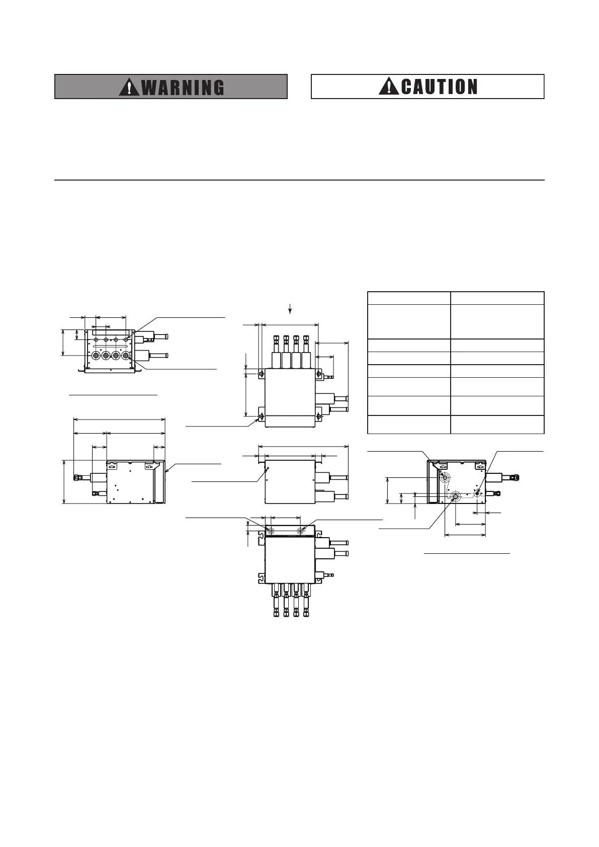
Outdoor Unit Connecting Side
Indoor Unit Connecting Side
(For Suspension Bolt)
34020
25630
60
67
67
352
551
Electrical Box
110
198
199
86
34
17635
Control Wiring Connection
(˜26)
Refrigerant Liquid Pipe
Connections
(4 x ˜9.52 Flare Nuts)
Refrigerant Gas Pipe
Connection
(4 x ˜15.88 Flare Nuts)
Power Supply Wiring
Connection (˜26)
Ground Terminal (M5)
(in Electrical Box)
60 x 3 = 180
38 30338
Refrigerant Gas
(High/Low Pressure)
Pipe Connection
(I.D. ˜22.36)
540
Suspension Bracket
4 - (12 x 32) Slotted Hole
42
60
156
50
180
244
60
(For Suspension Bolt)
Refrigerant Gas
(Low Pressure)
Pipe Connection
(I.D. ˜25.6)
Refrigerant Liquid
Pipe Connection
(I.D. ˜12.9)
View from P
1. Safety Summary
● Do not perform installation work, refrigerant
piping work or electrical wiring connection
without referring to our installation manual.
● Check that the ground wire is securely
connected.
● Connect a fuse of specied capacity.
Figure2.1DimensionsofSwitch Box
2. Structure
2.1 Dimensions
HCHM-N04X
Unit:mm
Specification
Model HCHM-N04X
PowerSupply
220-240V~50Hz
220V~ 60Hz
Input(W) 11.2
Refrigerant R410A
NetWeight(kg) 14
ConnectableIndoorUnit
TotalCapacity
16.0HPorless
ConnectableIndoorUnit
TotalCapacityperBranch
6.0HPorless
(Max.16.0kW)
NumberofConnectable
IndoorUnitperBranch
1to6
Do not install the Switch Box and
cable within approximately 3m (10 ft)
from strong electromagnetic wave
radiators such as medical equipment.
 Loading...