6
ENGLISH
Chapter 2 Installation
2.1 Product Description
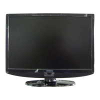
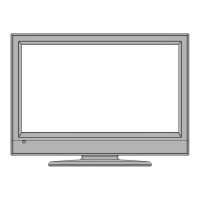
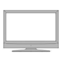
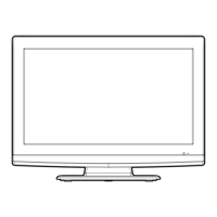
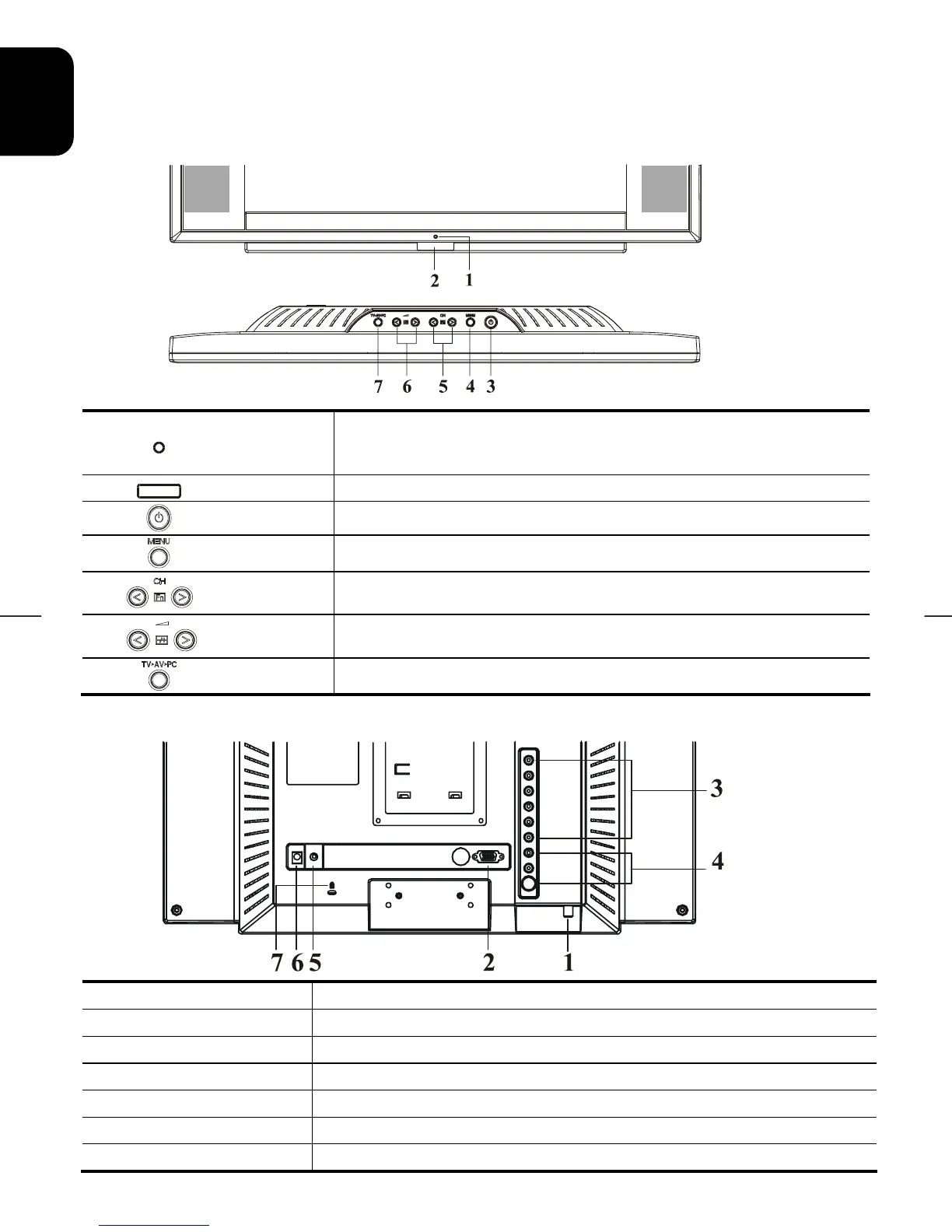
2.1.1 Front view of main body
Figure 2-1
Figure 2-2
1
Indicator for
Power
LED lights Green colour --- Power is ON.
LED lights Orange --- Monitor is in "Power Saving Mode".
LED is off --- Power is OFF.
2
IR receiver
IR receiver.
3
Power
Turn on or off the main unit.
4
Menu
Open or Close the OSD menu.
5
Channel
Select the next lower channel / higher channel (TV/AV mode) ; OSD
function for selecting (PC mode).
6
Volume
Lower / Raise the volume (TV/AV mode) ; OSD function for adjusting
(PC mode).
7
Source
Selection CABLE/TV, AV-1(S –VIDEO), AV-2(C-VIDEO) or PC.
2.1.2 Rear view of main body
Figure 2-3
1 RF in
Please connect to antenna or cable TV signal.
2 VGA input
Please use 15-pin VGA cable (Optional) to connect to PC.
3 AV2- IN
For composite (CVBS), component (Y, Cb, Cr) video input and audio.
4 AV1- IN
For S-video input and audio.
5 Phone in
Please connect the audio from sound card to PHONE IN. (Optional)
6 DC in
Please connect to your 12V power supply.
7 Kensington Lock hole
It can be secured with Kensington lock.
 Loading...