26
22” TFT TV Service Manual
• 5-band graphic equalizer for loudspeaker channel
• Spatial effect for loudspeaker channel
• Four Stereo SCART (line) inputs, one Mono input; two Stereo SCART outputs
• Complete SCART in/out switching matrix
• Two I
2
S inputs; one I
2
S output
• Dolby Pro Logic with DPL 351xA coprocessor
• All analog FM-Stereo A2 and satellite standards; AM-SECAM L standard
• Simultaneous demodulation of (very) high-deviation FM-Mono and NICAM
• Adaptive deemphasis for satellite (Wegener-Panda, acc. to ASTRA specification)
• ASTRA Digital Radio (ADR) together with DRP 3510A
• All NICAM standards
• Korean FM-Stereo A2 standard
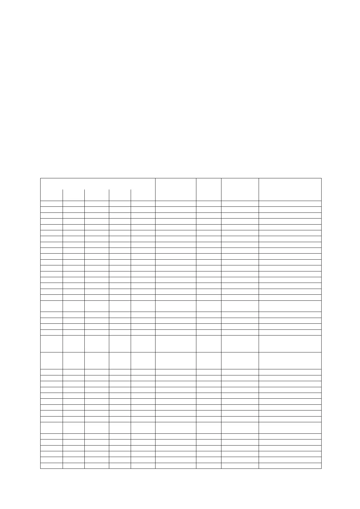
11.20.3. Pin connections
NC = not connected; leave vacant
LV = if not used, leave vacant
OBL = obligatory; connect as described in circuit diagram
DVSS: if not used, connect to DVSS
AHVSS: connect to AHVSS
Pin No. Pin Name Type
Connection
(if not used)
Short Description
PLCC
68-pin
PSDIP
64-pin
PSDIP
52-pin
PQFP
80-pin
PLQFP
64-pin
1 16 14 9 8 ADR_WS OUT LV ADR word strobe
2 - - - - NC LV Not connected
3 15 13 8 7 ADR_DA OUT LV ADR Data Output
4 14 12 7 6 I2S_DA_IN1 IN LV I
2
S1 data input
5 13 11 6 5 I2S_DA_OUT OUT LV I
2
S data output
6 12 10 5 4 I2S_WS IN/OUT LV I
2
S word strobe
7 11 9 4 3 I2S_CL IN/OUT LV I
2
S clock
8 10 8 3 2 I2C_DA IN/OUT OBL I
2
C data
9 9 7 2 1 I2C_CL IN/OUT OBL I
2
C clock
10 8 - 1 64 NC LV Not connected
11 7 6 80 63 STANDBYQ IN OBL Stand-by (low-active)
12 6 5 79 62 ADR_SEL IN OBL I
2
C bus address select
13 5 4 78 61 D_CTR_I/O_0 IN/OUT LV D_CTR_I/O_0
14 4 3 77 60 D_CTR_I/O_1 IN/OUT LV D_CTR_I/O_1
15 3 - 76 59 NC LV Not connected
16 2 - 75 58 NC LV Not connected
17 - - - - NC LV Not connected
18 1 2 74 57 AUD_CL_OUT OUT LV
Audio clock output
(18.432 MHz)
19 64 1 73 56 TP LV Test pin
20 63 52 72 55 XTAL_OUT OUT OBL Crystal oscillator
21 62 51 71 54 XTAL_IN IN OBL Crystal oscillator
22 61 50 70 53 TESTEN IN OBL Test pin
23 60 49 69 52 ANA_IN2+ IN
AVSS via
56 pF/LV
IF Input 2 (can be left
vacant, only if IF input 1 is
also not in use)
24 59 48 68 51 ANA_IN- IN
AVSS via
56 pF/LV
IF common (can be left
vacant, only if IF input 1 is
also not in use)
25 58 47 67 50 ANA_IN1+ IN LV IF input 1
26 57 46 66 49 AVSUP OBL Analog power supply 5V
- - - 65 - AVSUP OBL Analog power supply 5V
- - - 64 - NC LV Not connected
- - - 63 - NC LV Not connected
27 56 45 62 48 AVSS OBL Analog ground
- - - 61 - AVSS OBL Analog ground
28 55 44 60 47 MONO_IN IN LV Mono input
- - - 59 - NC LV Not connected
29 54 43 58 46 VREFTOP OBL
Reference voltage IF A/D
converter
30 53 42 57 45 SC1_IN_R IN LV SCART 1 input, right
31 52 41 56 44 SC1_IN_L IN LV SCART 1 input, left
32 51 - 55 43 ASG1 AHVSS Analog Shield Ground 1
33 50 40 54 42 SC2_IN_R IN LV SCART 2 input, right
34 49 39 53 41 SC2_IN_L IN LV SCART 2 input, left
35 48 - 52 40 ASG2 AHVSS Analog Shield Ground 2