ABOUT THE SYSTEM SYSTEM REAR VIEW
7
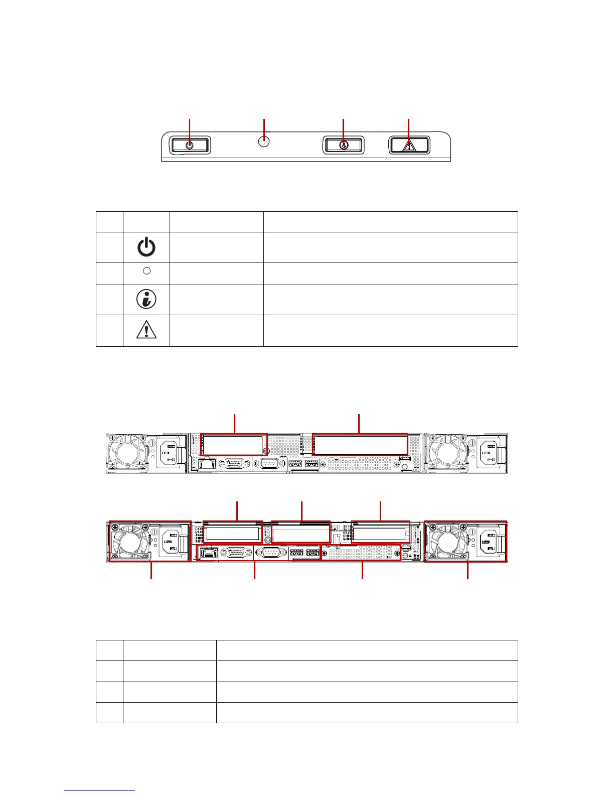
Front Control Panel (FCP)
System Rear View
Figure 3. Front Control Panel
Table 4: Fr
ont Control Panel Descriptions
NO.ICON NAME DESCRIPTIONS
1
Power button with
LED
Power on / off
Blue on - S0 system power on; Off - S5 system power off
2 Reset button Soft reset system function
3
Identification button
with LED
Toggles ID LED, activate ID LED to identify system
Blue blinking - Identifier on front and rear chassis; Off - Normal.
4System Status LED
Provides critical and non-critical failure notification
Amber blinking - failed; Off - SEL cleared / good
Table 5: System Rear View
NO.FEATURE DESCRIPTIONS
1 Power sub-system
Main power supply unit (PSU0). See Power Sub-System on page 9.
2 System I/O ports
See System Rear I/O on page 8
3 Expansion slot Support OCP 2.0 mezzanine card installation (CPU0)