LED STATUS DESCRIPTIONS
12
ABOUT THE SYSTEM
LED Status Descriptions
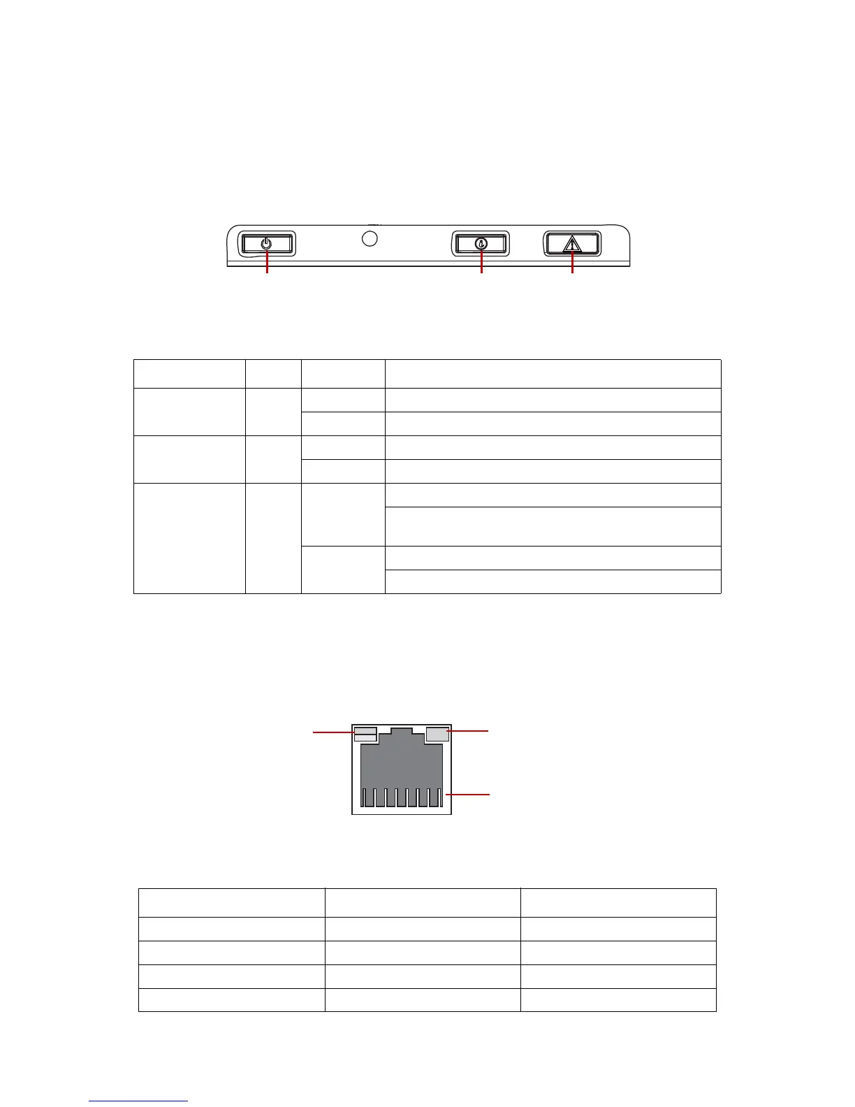
Front Control Panel LEDs
For location of the FCP, see System Front View on
page 6.
Figure 9.
Front Control Panel LEDs
BMC Management Port LEDs
The system mainboard includes one dedicated RJ45 GbE management port. The RJ45 con-
nector has two built-in LEDs. See the following illustration and table for details.
Table 13: Front Control Panel LEDs Behavior
NAME COLOR CONDITION LED STATUS DESCRIPTIONS
Power LED Blue
On System S0 power on
Off System S5 power off
Identification Blue
Blinking Unit selected for identification
Off No identification request
Status LED Amber
Blinking
Critical Failure: critical fan, voltage, temperature state.
Non-Critical Failure: non-critical fan, voltage, temperature
state, CPU thermal trip, DC off.
Off
SEL cleared
Last pending warning or error has been de-asserted.
Figure 10. GbE RJ45 Management Port
Table 14: RJ45 LED Descriptions
CONDITION LINK ACTIVITY
Unplugged Off Off
1G active link On amber Blinking green
100M active link On green Blinking green
10M active link Off Blinking green
 Loading...