--- 49 ---
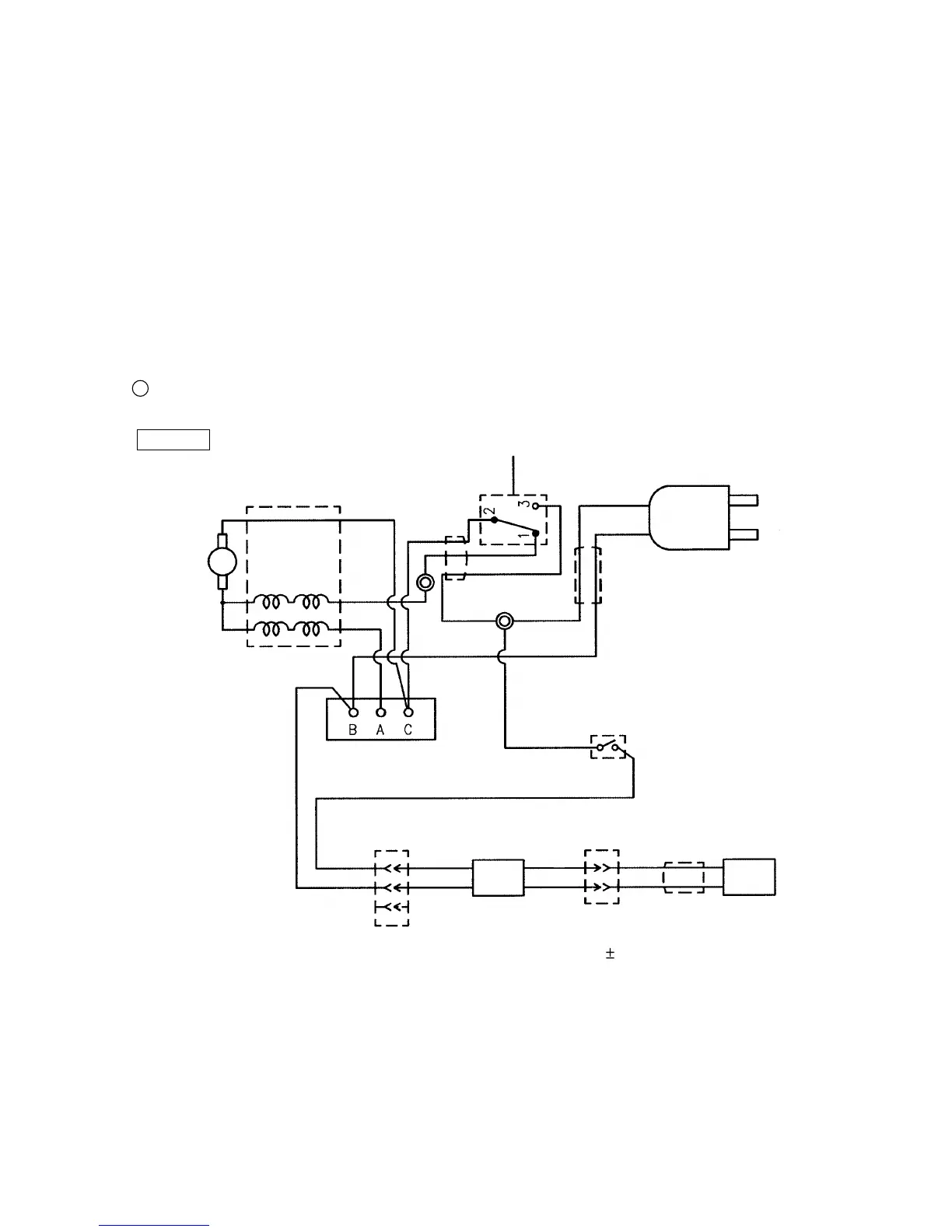
11-4. Wiring Diagram
The Models C 10FSH and C 10FSB are equipped with an overload protection circuit.
Carefully ensure that wiring is accomplished as illustrated below. As incorrect wiring will result in lack of rotation,
reverse rotation or other malfunctions, close attention is absolutely necessary.
[WARNING] Be sure to turn off the Switch (W/Cover) [156] on the side of the handle and unplug the power
cord plug from the receptacle before replacing the Laser Marker [99] and the Switching Power
Supply [144]. Do not disconnect Connector (B) [145] that connects the Laser Marker [99] with
the Switching Power Supply [144] while the Laser Marker [99] is lighting. Otherwise, the Laser
Marker [99] may be damaged due to surge (electricity stored in the Switching Power Supply
[144]). Do not stare into beam while the Laser Marker [99] is lighting.
SW
Armature
ass'y
Black
Input
AC 120 V
Fig. 69-1
C 10FSH USA/CAN
Black
Laser module
Controller ass'y
Blue
White
SW
Red
White
Red
Black
Black
White
These numbers indicate the terminal
numbers of the trigger switch.
White dotted line
on the black
Stator ass'y
Stator coil
Brake coil
Yellow
Gray
White
Black
AC 120 V
DC 6 0.5 V
Red
OFF
Power
module
Black
1 Wiring diagram

 Loading...