ABOUT THE SYSTEM SYSTEM REAR VIEW
1-9
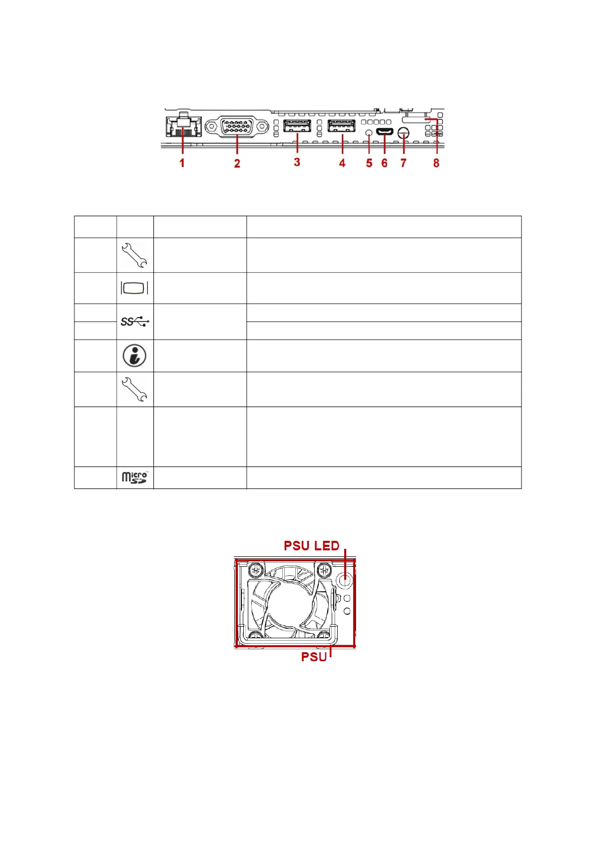
System Rear I/O
Figure 1-4. System Rear I/O
Power Sub-System
Figure 1-5. PSU to Mainboard Module Description
A single power supply unit (default) is supplied in the system. A secondary PSU is available
for redundancy functionality.
Table 5: System Rear I/O Definition
NO. ICON NAME DESCRIPTION
1. Dedicated NIC Dedicated RJ45 connector
2. VGA connector
Maximum display resolution: 1920x1200 32bpp@60Hz
(reduced blanking)
3.
USB 3.0 port
USB 1 port; connect to USB device
4. USB 0 port; connect to USB device
5. Identification LED Blue blinking - Identifier; Off - Normal
6. Micro USB port Transmit in serial signal for debug or terminal concentrator
7.
PFR Status LED
(Only for certain
models)
Off: Power Off/PFR Module is not installed
Green On: Authenticated
Amber On: Failed
Amber Blinking: Authentication /Recovery is executing in T-1
8. MicroSD slot Backup BMC SEL.

 Loading...
