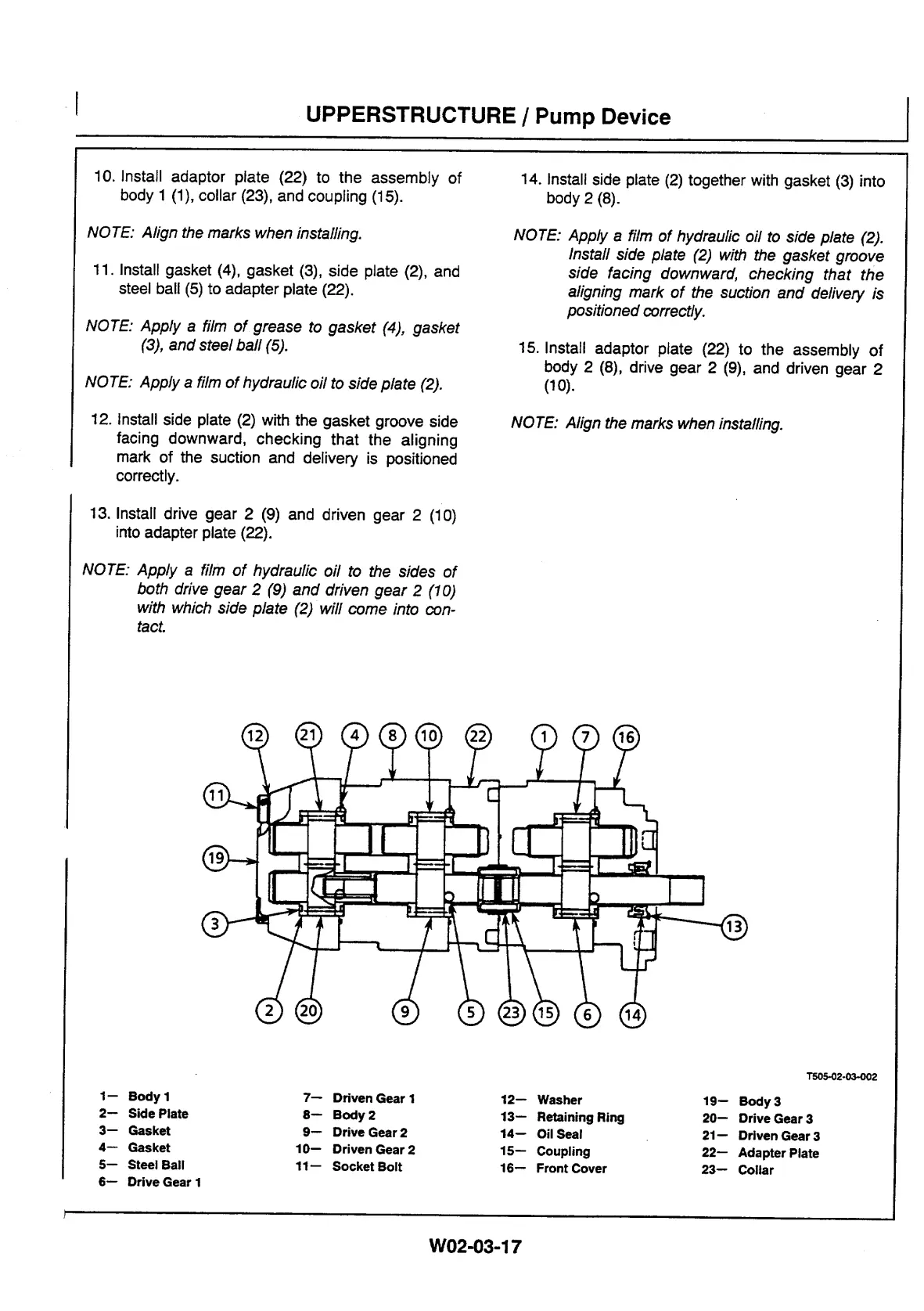
10. Install adaptor plate (22) to the assembly of
body 1 (1), collar (23), and coupling (15).
NOTE: Align the marks when installing.
11. Install gasket (4), gasket (3), side plate (2), and
steel ball (5) to adapter plate (22).
NOTE: Apply a film of grease to gasket (4), gasket
(3), and steel ball (5).
NOTE: Apply a film of hydraulic oil to side plate (2).
12. Install side plate (2) with the gasket groove side
facing downward, checking that the aligning
mark of the suction and delivery is positioned
correctly.
14.
Install side plate (2) together with gasket (3) into
body 2 (8).
NOTE: Apply a film of hydraulic oil to side plate (2).
Install side plate (2) with the gasket groove
side facing downward, checking that the
aligning mark of the suction and delivery is
positioned correctly.
15.
Install adaptor plate (22) to the assembly of
body 2 (8), drive gear 2 (9), and driven gear 2
(10).
NOTE: Align the marks when installing.
13. Install drive gear 2 (9) and driven gear 2 (10)
into adapter plate (22).
NOTE: Apply a film of hydraulic oil to the sides of
both drive gear 2 (9) and driven gear 2 (10)
with which side plate (2) will come into con-
tact.
T505-02-03-002
1—
Body 1
7—
Driven Gear 1
12—
Washer
19—
Body 3
2—
Side Plate
8—
Body 2
13—
Retaining Ring
20—
Drive Gear 3
3—
Gasket
9—
Drive Gear 2
14—
Oil Seal
21—
Driven Gear 3
4—
Gasket
10—
Driven Gear 2
15—
Coupling
22—
Adapter Plate
5—
Steel Ball
11—
Socket Bolt
16—
Front Cover
23—
Collar
6—
Drive Gear 1
UPPERSTRUCTURE / Pump Device
W02-03-17



 To Next Page