--- 13 ---
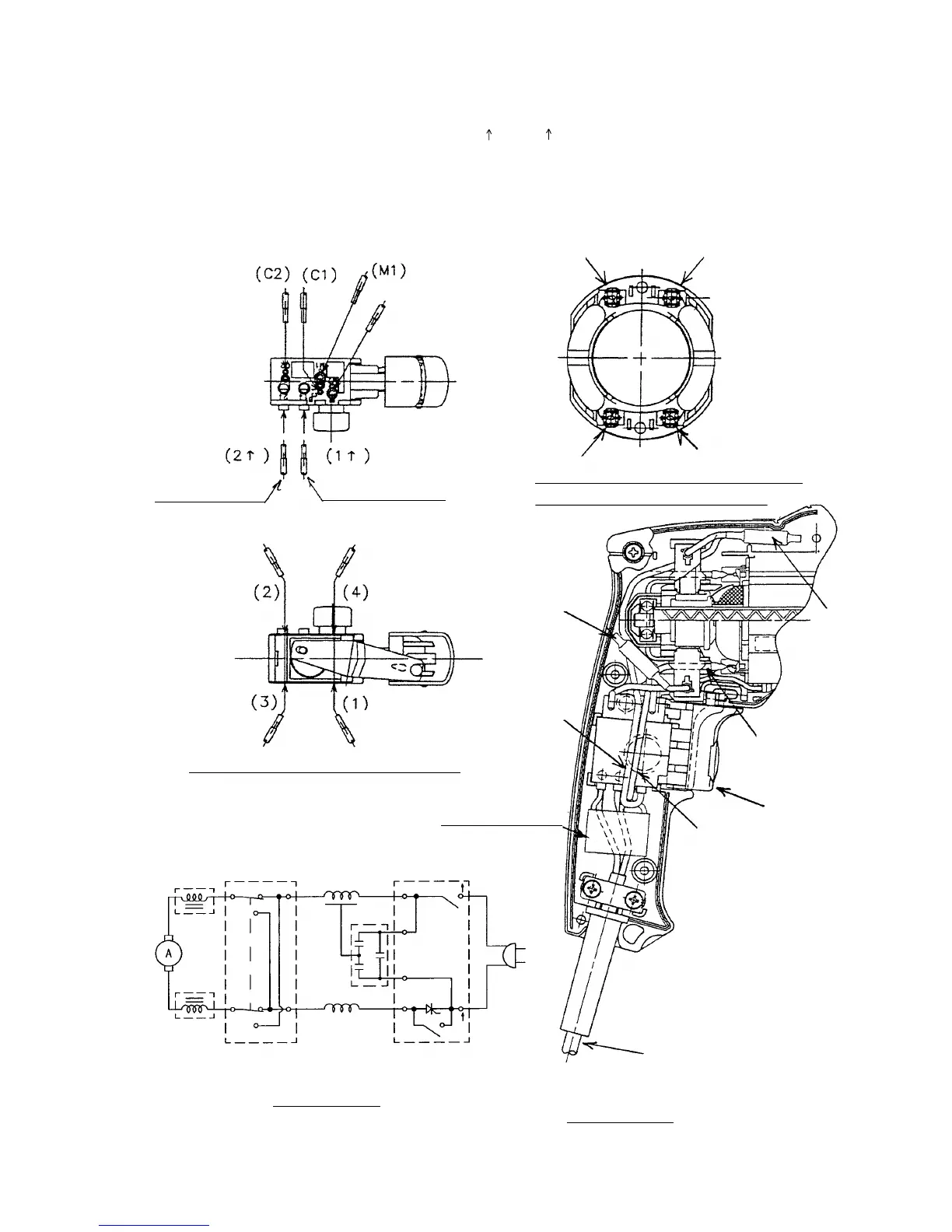
8-5. Wiring Diagram and Lead Wire Arrangements
Conduct wiring in accordance with the diagrams and arrangements illustrated below.
The symbonls (1), (2), (3), (4), (M1), (M2), (C1), (C2), (1 ) and (2 ) in the diagrams correspond to switch terminal
figures.
(1) For models with noise suppressor and choke coils
(Brown)
(Gray)
(White)
(Blue)
(Red)
Switch
Noise suppressor
Cord
Wiring diagram
Forward/reverse
push-button section
(White)
(Gray)
(Black)
(Red)
Housing (B) side
Housing (A)
side
(Gray)
(Red)
(M2)
For noise
suppressor (Black)
For cord
(Blue or white)
For cord
(Brown or black)
(Blue)
(Black)
(Brown)
(White)
Connection of internal wires to the stator
(Viewed from the commutator side)
Connection of internal wires to the switch
Main switch section
Choke coil
(Blue or white)
Choke coil
(Blue)
(Brown)
(Brown or black)
(Gray)
(Black)
ST
ST
(Red)
(White)
(3)
(2)
(1)
(4)
(M1)
(C1)
(C2)
(M2)
(2 )
(1 )
Cord
Noise
suppressor
Wiring diagram