--- 13 ---
Structure of the Neidhardt spring
The main body (back cover) is connected to the
lower handle through four cylindrical rubbers (handle
dampers). The shaft fixed to the handle is turned in
conjunction with the handle movement and the
rubbers are rolled and compressed to absorb the
vibration. The Neidhardt spring prevents the handle
from moving horizontally. Thus the Model H 45MRY
can provide high vibration-proofing effect without
hindering the operability by twisting. In addition, the
handle is prevented from being pulled out (Fig. 5).
Compressed by turning
Rebound
Turning direction
of the handle
Fig. 5
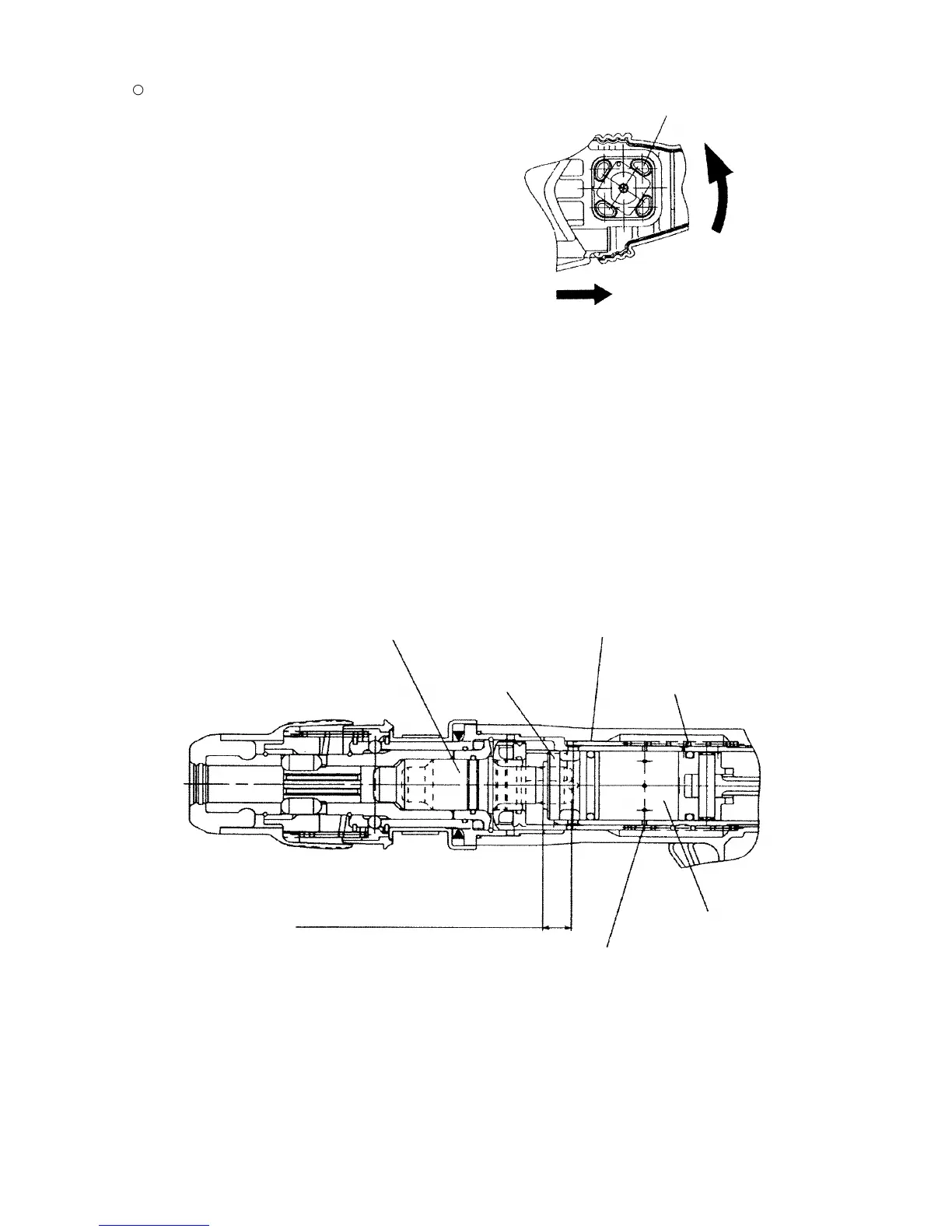
8-4. Idling-proof Mechanism
When the bull point is released from the concrete surface, the slide sleeve and the second hammer are forcibly
moved to the position illustrated in Fig. 6 by spring (B), and the striker moves out of striking position. When this
occurs, the air holes located at the position unaffected by the rebound of the striker at no load are opened and the
pressure within the air chamber remains unchanged even though the piston continues to reciprocate, thereby
preventing striking operation.
Fig. 6
Striker
Slide sleeve
Second hammer
Forward movement of
second hammer & striker
Spring (B)
Air hole
Air chamber
 Loading...