PMML0175A-rev.1 - 6/2008
HARC-MODBUS - xxxxxxxxxxxxxxxx
7
English
HARC-MODBUS - Installation Manual
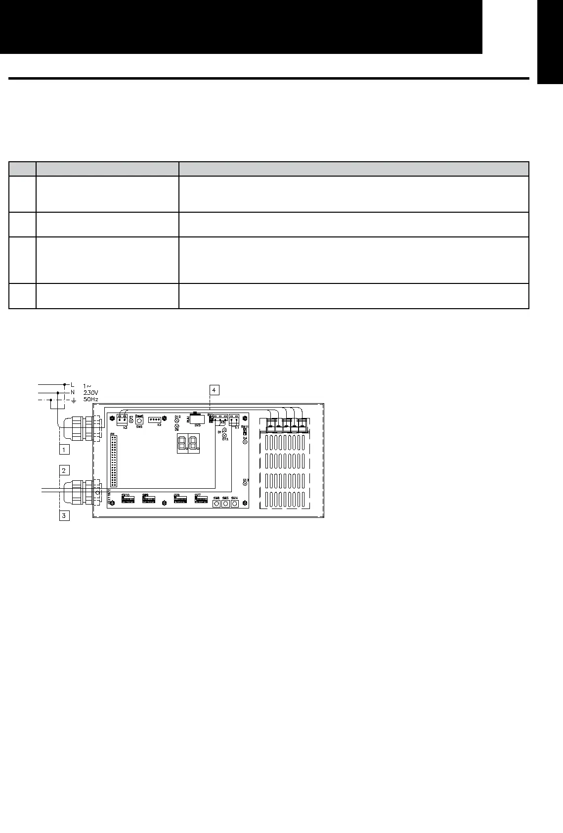
5. Wiring connections
5.1 Electrical wiring
In order to run, HARC-MODBUS must be connected to the corresponding input and output signals, power supply cables and H-
LINK.
No. Connection Cable Specifications
1
Power supply circuit
1~ 230V 50Hz 25W
(With protection circuit)
Select wires according local regulations
(recommended minimum 1.5mm² H05RN-F)
2
MODBUS 3 cables harness 0.75mm² (H05RN-F type). Use different colour for each cable.
(Serial Port RS485)
3
H-LINK Communication cables for the connection of HARC-MODBUS to an Hitachi installation,
via CSNET WEB or any Hitachi unit using same H-LINK terminals.
Twisted pair shielded cable 0.75mm² (H05RN-F TYPE).
Shield must be grounded in one side only.
4
PCBs Power supply
+5V DC. Imax.= 5A DC
Pair cable 0.75mm² (H05RN-F TYPE)
Note:
All cables, except 4 are field supplied.
Field supplied Protections:
CB/EF: 5A
ELB: 2/40A/30mA
CB: Circuit Breaker
EF: Electric Fuse
ELB: Earth Leakage Breaker

 Loading...


