Chapter 2 Specifications
2 – 2
2.2 Performance specifications
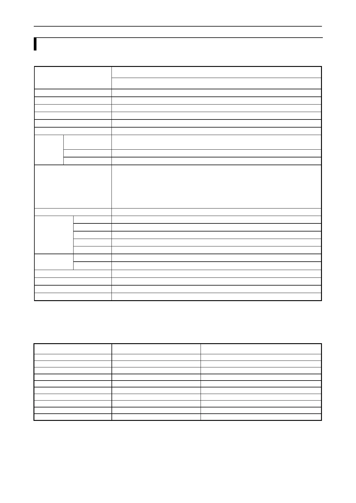
Table 2.2 Performance specifications
MV-*20** / MV-*40** / MV-*64**
256KB (incl. 64KB persistent variables)
No. of I/O (using 64 points unit)
320 (input: 200, output: 120)
Single phase: 100kHz×5ch. (32bit)
2-phase: 60kHz×2ch. (32bit)
IEC61131-3 compliant 5 languages
LD: Ladder Logic Diagram
FBD: Function Block Diagram (incl. CFC : Continuous Function Chart)
SFC: Sequential Function Chart
IL: Instruction List
ST: Structured Text
USB 2.0 Full speed (Gateway (*2))
10BASE-T/100BASE-TX (Gateway (*2), EtherCAT master (*3), Modbus-TCP master (*3) /slave)
RS-232C (Modbus-RTU master/slave, General purpose)
RS-422/485 (Modbus-RTU master/slave, General purpose)
POW LED, RUN LED, OK LED, STATUS LED
STOP / RUN (Remote STOP/RUN enabled when the switch position is RUN.)
Support (Program transfer, Data logging, Web visualization)
MV-BAT (for retentive data and Real time clock)
Diagnosis (micro processor error, watch dog timer error, memory error, battery error, etc.)
*1 Since a boot project contains about 23KB of service information besides program, available memory size for user program is
about 1000KB instead of 1024KB (1MB).
*2 Gateway: Communication with EHV-CODESYS / HX-CODESYS
*3 ErherCAT master and Modbus-TCP master are supported by CPU ROM VER. 3.5.3.42 or newer version.
Table 2.3 Processing speed
Data type (number of bit)
Processing time [μs / IL]