Chapter 2 Specifications
2 – 19
2.16 40-point Basic unit
2.16.1 Name and function of each part
Name and function of each part
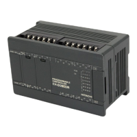
MV-A40DR, MV-D40DR, MV-D40DT, MV-D40DTPS
MV-A40DR : 570g (1.25 lb.)
MV-D40DR : 500g (1.10 lb.)
MV-D40DT : 460g (1.01 lb.)
MV-D40DTPS : 460g (1.01 lb.)
[Without the front cover]
(1)POW LED
(2)OK LED
(3)RUN LED
(4)STATUS LED
(6)Communication port cover
(10)Expansion connector cover
(12)DIN rail installation clip
(18)USB communication port
(23)Option board connector
(21)USB memory port
Setting switch
USB memory operation LED
indicates that the power is supplied.
represents the result of the self-diagnosis in the basic unit.
Normal: ON, Abnormal: blink or OFF (Refer to Section 3.26 Troubleshooting)
displays the operating condition. (RUN: ON, STOP: OFF)
blinks until the state in which PLC can RUN from power-up (500ms ON / 500ms OFF) or during
writing the program to FLASH memory.
When signal status is ON, LED lights up accordingly.
The cover for RUN/STOP switch, serial port and USB communication port.
The cover for Ethernet port and USB memory port.
The cover for the battery connector.
The cover for the option board connector.
Avoid contact with the printed circuit board when you remove the cover.
Expansion connector cover
The cover for the expansion connector.
The cover for the terminal block.

 Loading...