14.7 REFRIGERANT PUMP DOWN
When the refrigerant should be collected into the outdoor unit due
to indoor/outdoor unit relocation, collect the refrigerant as follows:
1 Attach the manifold gauge to the gas stop valve and the liquid
stop valve
2 Turn ON the power source
3 Set the DSW1-1 pin of the outdoor unit PCB at the “ON” side
for cooling operation. Close the liquid stop valve and collect
the refrigerant.
4 When the pressure at lower pressure side (gas stop valve)
indicates -0.01 MPa (-100 mmHg), perform the following pro-
cedures immediately.
- Close the gas stop valve.
- Set the DSW1-1 pin at the “OFF” side (To stop the unit
operation).
5 Turn OFF the power source.
CAUTION
Measure the low pressure by the pressure gauge and keep it not
to decrease than -0.01 MPa. If the pressure is lower than -0.01
MPa, the compressor may be faulty.
15 DRAIN PIPING
15.1 DRAIN DISCHARGING BOSS
15
When the base of the outdoor unit is temporarily utilized as a dra-
in receiver and the drain water in it is discharged, this drain boss
is utilized to connect the drain piping.
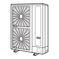
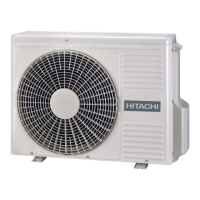
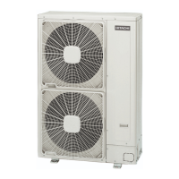
Model Applicable Model
DBS-12L
RAS-(2/2.5)HVNP1
RAS-3HVNC1
RAS-3HVRNS3
Connecting procedure
1 Insert the plastic cap into the drain boss up to the extruded
portions.
2 Insert the boss into the unit base up to the extruded portions.
3 Size of the drain boss is 15 mm (O.D.)
4 A drain pipe should be eld-supplied.
NOTE
• Do not use this drain boss set in a cold area, because the
drain water may freeze.
• This drain boss is not sufcient to collect all the drain water. If
collecting drain water is completely required, provide a drain-
pan that is bigger than the unit base and install it under the
unit with drainage.
Drain pipe
Plastic cap
Plastic cap
Drain hole
100 mm
Plastic cap
Drain hole
Push Push
≥ O.D. ∅ 16 mm
Speciers/installers have responsibility to follow local codes and
regulation which specify safety requirements against refrigerant
leakage.
14.8.1 Maximum permissible concentration of HCFC/
HFC gas
The refrigerant R410A, charged in the system, is an incombusti-
ble and non-toxic gas. However, if leakage occurs and gas lls a
room, it may cause suffocation.
The maximum permissible concentration of HCFC/HFC gas,
R410A in air is 0.44 kg/m³, according to EN378-1.
Therefore, some effective measure must be taken to lower the
R410A concentration in air below 0.44 kg/m³, in case of leakage.
14.8.2 Calculation of refrigerant concentration
1 Calculate the total quantity of refrigerant R (kg) charged in
the system connecting all the indoor units of rooms to be air-
conditioned.
2 Calculate the room Volume V (m³) of each room.
3 Calculate the refrigerant concentration C (kg/m³) of the room
according to the following equation:
R R: Total quantity of charged refrigerant (kg)
≤ C V: Room volume (m³)
V C: Refrigerant concentration 0.44 kg/m³ for R410A
14.8.3 Countermeasure for refrigerant leakage
1 Provide a shutterless opening which allow fresh air to circula-
te into the room.
2 Provide a doorless opening of 0.15% or more size to the oor
area.
3 Pay a special attention to the place, such as a basement, etc.,
where refrigerant can stay, since refrigerant is heavier than
air.
14.8 CAUTION ON REFRIGERANT LEAKAGE

 Loading...


