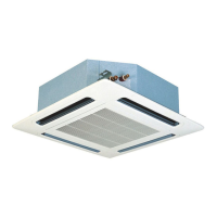
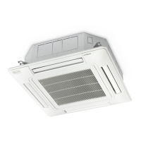
RPK-2.0FSN2M
Nº Part
1 Earthing wire
2 Inlet thermistor
3 Receiver part
4 Electrical box cover
5 Screw
Remove the front panel as indicated in section Removal of the front
panel, see on page 323.
Removal a screw from the electrical box cover.
Remove the connector from the main PCB.
Nº
Part
1 Board base 2
2 Hook
3 Main PCB
4 Board base 1
5 Terminal board
Remove the two hooks from base 1 of the PCB to which the PCB
is attached. Lift base 1 and remove the remaining connectors.
First remove the heat exchanger earthing cable and remove the
two aforementioned connectors and a hook from base 2 of the
PCB. Lift base 2 and remove the remaining connectors.
After replacing the PCB, insert the connectors back into the PCB
following the procedure in reverse order. Be careful not to catch
any wire between the components, with incorrect or barely visible
connections.
Also make sure you do not bend any part of the PCB with the
components, such as the rings or the connectors.
10 Servicing
334
SMGB0063 rev. 1 - 10/2010

 Loading...


